User
Options
The User Options section
in Document Options enables you to set
up your working preferences. You might, for example, want to specify how
the snap operation will work or how much information will be displayed
on your plot.
General tab
Options on the General
tab contain settings for current scenes as well as general display
options.
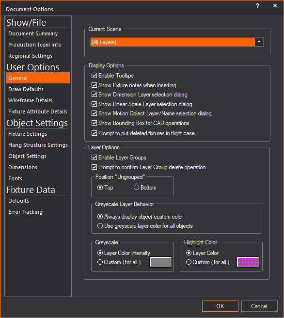
- Current Scene:
The current layer shown on the plot. The current scene can also be
changed on the Scene toolbar.
Display Options
General display preferences.
- Enable
Tooltips: Displays tooltips
on your drawing. Tooltips are pop-up messages that display specific
information about a fixture or object when you hover over it in Wireframe
view.
A tooltip appears and displays the object information,
including name (if applicable), layer, and other details such as the number
of vertices and faces that make up the object.
Tip: The
number of vertices and face counts in tooltips can help you determine
which object impedes the Shaded view performance.
- Show Fixture notes when
inserting: Select this checkbox to display the fixture notes
when you are hanging fixtures, if applicable to the selected fixture.
- Show Dimension Layer selection
dialog: Select this checkbox to be prompted to select a layer
when inserting a new dimension.
- Show Linear Scale Layer
selection dialog: Select this checkbox to be prompted to select
a layer when inserting a new linear scale.
- Show Motion Object Layer/Name
selection dialog: Select this checkbox to be prompted to select
a layer when inserting a new motion object.
- Show Bounding Box for
CAD operations: Select this checkbox to enable a framing outline
or bounding box to appear as a substitute placeholder to objects when
scaling or rotating in CAD. Using the bounding box improves the performance
of Scale and Rotate
tools.
- Prompt to put deleted
fixtures in flight case: Select this checkbox to be prompted
when you delete a fixture. You will be prompted to delete it completely
or send it to the Flight Case. If you choose to send it to the Flight
Case, the fixture is reserved for you in case you want to reinsert
it.
Layer Options
Choose how layers are displayed in the
Layer Database and highlighted in
your drawing.
- Enable Layer Groups:
Select this checkbox to display the layers in the Layer Database as
items organized in Layer groups. Clear this checkbox to display Layers
as a list. New Layer Groups are created in the Layer
Database window. The Layer Groups and the list of layers
will be displayed in the Layer Database and
Properties windows.
- Prompt to confirm Layer
Group delete operation: Select this checkbox to be prompted
to delete the selected Layer Group.
- Position “Ungrouped”:
Choose where the Ungrouped Layer Group is displayed in the Layer
Database window.
- Top: Select this
option to display the ungrouped layers at the top of the list of layers
in the Layer Database window.
- Bottom: Select
this option to display the ungrouped layers at the bottom of the list
of layers in the Layer Database window.
Greyscale Layer Behavior
Choose how the objects in the layer(s)
will be displayed when the layer(s) are set to greyscale.
- Always display object
custom color: When you select this option, objects that were
set to a custom color (in Object Properties) will always be displayed
in the custom color even if the object’s layer is in greyscale.
- Use greyscale layer for
all objects: When you select this option, objects that were
set to the layer color or a custom color will be displayed in greyscale
when the layer(s) for all objects are in greyscale.
- Greyscale: Set
the greyscale intensity for the selected layer(s).
- Layer Color Intensity:
Select this option to display the layer in greyscale with the same
intensity as that of the layer’s set color.
- Custom (for all):
Select this option and click the box to adjust the greyscale intensity
for all the objects in the selected layer(s).
- Highlight Color:
Set the color for the highlighted layer.
- Layer Color: Select
this option to display the highlighted layer with the color of the
layer.
- Custom (for all):
Select this option and click the color select box to select the color
for all the objects in the highlighted layer.
Draw
Defaults tab
Options on the Draw
Defaults tab affect general preferences for snap, grid, and
units settings.
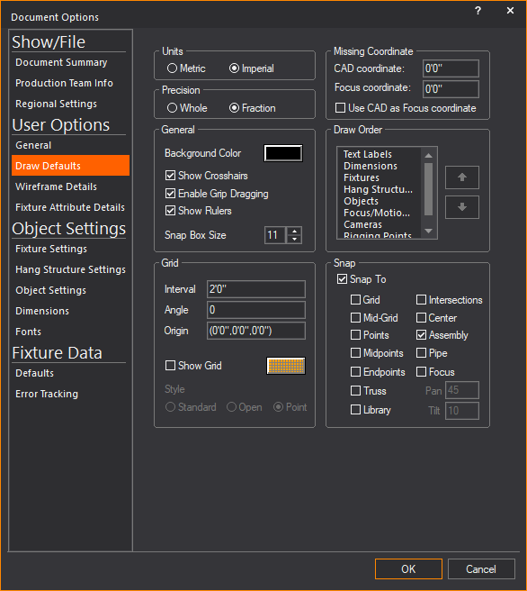
- Units: The units
of measurement used in WYSIWYG. For more information on these units,
see Metric
vs. Imperial. The units can be toggled from metric to imperial
at any time by double-clicking the units display on the Status bar.
- Precision:
This option affects the units of drawing precision. For more information
on these units, see Coordinate
notation. Based on your choice for measurement units, you
can choose to display the drawing precision in centimeters, millimeters,
whole numbers, or fractions.
General
Options that affect the general appearance
and ability to work in Wireframe views.
- Background Color: The color
that will be used in all wireframe views. Click the box to choose
a different color.
- Show Crosshairs:
Select this checkbox to set the cursor display to use cross hairs
in plot views. Cross hairs are useful for lining up objects.
- Enable Grip Dragging:
Select this checkbox to resize objects by clicking and dragging on
their markers.
- Show Ruler: Select
this checkbox to show the rulers in drawing modes.
- Snap Box Size: Sets
the size of the snap box that appears around the cursor when in snap
mode. Consequently, this affects how close the cursor must be to the
objects before the snap is applied.
Grid
Options that affect the drawing grid.
- Interval:
Select the spacing between points on the drawing grid. Although the
WYSIWYG drawing grid might not be visible, it exists in the background.
The settings in this group box are important when using the snap to
grid tool. For more information on this tool, see Snaps.
- Angle: Select the
angle of rotation for the drawing grid. Although the WYSIWYG drawing
grid might not be visible, it exists in the background. The settings
in this group box are important when using the snap to grid tool.
For more information on this tool, see Snaps.
- Origin:
The point of origin. For more information on the origin, see Coordinate
system and origin.
- Show Grid: Select
this checkbox if you want to add a grid to your wireframe view (in
every view except isometric).
- Grid Color: Click
this box to choose the color that grid lines will be displayed as
in the Wireframe view.
- Style: You can
also choose the style of the grid by selecting the appropriate option
button.
- Standard creates
a grid with evenly spaced, closed squares.
- Open creates
a grid with open squares.
- Point creates
a grid of dots.
The lines in the resulting grid are spaced
at the interval specified in the Interval box.
If the interval is short, you may have to zoom in on your plot to see
the gridlines.
Missing Coordinate
Sets missing coordinate options. For more
information on missing coordinates, see The
missing coordinate.
- CAD coordinate:
The missing coordinate in CAD mode.
- Focus coordinate:
The missing coordinate when manually focusing fixtures.
- Use CAD as Focus coordinate:
Select this checkbox to use the same missing coordinate for Focus
coordinate as CAD coordinate.
- Draw Order: Arrange
the order in which fixtures, hang structures, and objects will be
drawn in your model by selecting the items and moving them up or down
with the arrow buttons. Whichever item appears at the top of this
box will always appear on top of the other items in your model.
Example: If
you leave the default order of Fixtures > Hang
Structures > Objects, then fixtures will always appear on top
of truss and truss will always appear on top of all other objects, regardless
of how you arrange them via the and/or
commands. For more information
on these commands, see Sending to back/bringing to front.
- Snap:
Enables or disables the snap function. For more information, see Snaps.
Snap tools can be toggled at any time using the tools on the CAD Options toolbar.
Wireframe Details
tab
The Wireframe Details tab
affect what and how fixtures, hang structures, objects, text, and information
are displayed.
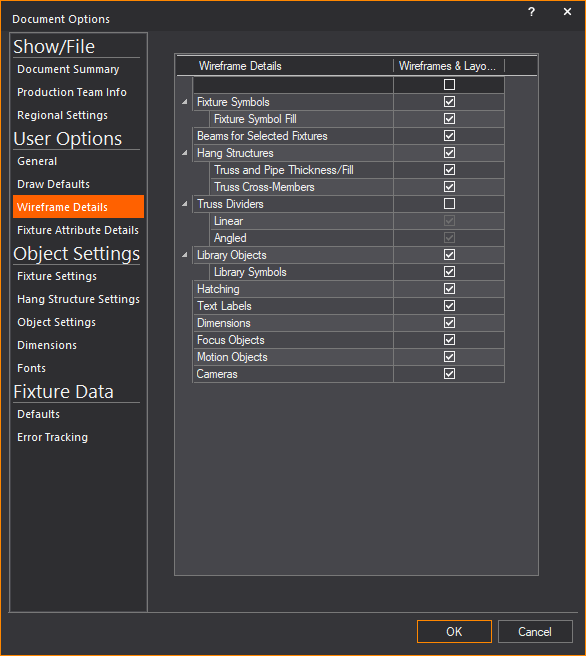
- Wireframes & Layouts:
Select to display information and drawing details of the object in
Wireframe views, Layouts, and Plots.
Tips:
- Select the checkbox on the top row of the list
to select all checkboxes below.
- Click the arrows in the leftmost column to expand
and display the rows with additional options.
- Fixture Symbols:
Select this checkbox to always show 2D symbols in 2D wireframe views,
and then select the option below. When this option is disabled, fixtures
will be displayed as 3D models instead of their 2D symbols.
- Fixture Symbol Fill:
Select this checkbox to always show filled 2D Fixture Symbols in wireframe
views.
- Beams
for Selected Fixtures: Select this checkbox to automatically
turn on beams w hen selecting
a fixture on your drawing. If this checkbox is not selected, the beam
is not visible when you select a fixture.
Note: Only
applies to CAD and DATA modes.
- Hang Structures:
Select this checkbox to always show truss and pipes in wireframe views,
and then select the options below.
- Truss and Pipe Thickness/Fill:
Select this checkbox to always show filled 2D Pipe and Truss objects
with chords and cross-member thickness.
- Truss
Cross-Members: Clear this checkbox to hide truss cross members
on your drawing to reduce the clutter or to increase the speed of
the display. Select this checkbox to see the cross members.
- Truss Dividers:
Truss Dividers show where the breaks in your truss sections are for
quick assembly on site and ease-of-use for rental shops and other
personnel who need to analyze your truss configuration. Select the
Truss Dividers checkbox to enable this
feature, and then select the options below. For more information on
using this feature, see Configuring
truss dividers.
- Linear: Select
this checkbox to show the lines that appear parallel to the ends of
your truss sections. These lines are always thick and can be colored
any way you choose.
- Angled: Select
this checkbox to show the lines that appear at the junction of truss
sections on a 45 degree angle with the truss end. The Angled Section
dividers can be thick or thin, and can be colored any way you choose.
- Library Objects:
Select this checkbox to always show library objects in wireframe views
and then select the option below.
- Library Symbols:
Select this checkbox to always show library objects as 2D symbols
in wireframe views. When this option is disabled, library objects
will be displayed as 3D models instead of their 2D symbols.
- Hatching: Select
this checkbox to always show hatching styles assigned to objects in
wireframe views.
- Text Labels: Select
this checkbox to always show text labels in wireframe views.
- Dimensions: Select
this checkbox to always show dimensions in wireframe views.
- Focus Objects:
Select this checkbox to always show focus objects in wireframe views.
- Motion Objects:
Select this checkbox to show objects set with motion in wireframe
views.
- Cameras: Select
this checkbox to always show Cameras in wireframe views.
Fixture Attribute
Details tab
The Fixtures Attribute
Details tab affect where, what, how fixture information are
displayed.
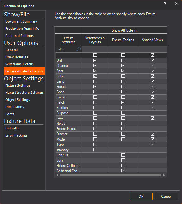
- Wireframes & Layouts:
Select the checkboxes in this column to always display the selected
fixture information in Wireframe views, Layouts and Plots.
- Fixture Tooltips:
Select the checkboxes in this column to always display the selected
fixture information on fixture tooltips when your cursor hovers over
the fixture in Wireframe views.
- Shaded Views: Select
the checkboxes in this column to always display the selected fixture
information when your cursor hovers over the fixture in Shaded view.
Select the checkbox on the top row of the
Wireframes & Layouts, or Fixture
Tooltips, or Shaded Views column
to select all checkboxes in the column.