 The Set User Origin button.
When drawing in WYSIWYG, you are drawing in real scale (1:1). When you create a drawing in CAD, you are generating a virtual representation of your real set-up. If you were to do this on paper by hand, you would need to draw a scaled-down version of your space. However, since there are no paper size limitations in CAD mode, you can draw your venue, sets, pipes, trusses, and lighting fixtures in real scale.
Scaling down for printing purposes is done during print set-up and in the Presentation (PRES) mode when creating plots. These settings allow you to print your drawings in whatever scales are necessary without having to redraw anything.
When working in CAD, you are working in a 3D environment (even in WYSIWYG Report). Objects are drawn as 3D objects, with width, depth, and height values using the Cartesian coordinate system of 3 working axes X, Y, and Z. The point where the 3 axes meet is called the origin and the value of X, Y, and Z is 0 respectively (0,0,0).
By default, the origin is set at the center point of the WYSIWYG venue that you insert. Inserting venues is discussed in Drawing a venue. You can reset the origin to another point in your drawing; you can set a user origin so that a different point will assume the values (0,0,0).
Tip: You can also use the Set User Origin tool on the Tools toolbar.
The Set User Origin button.
Result: This resets the origin back to the WYSIWYG default.
When entering coordinates in WYSIWYG, you can specify a location or distance in either inch fractions (to the sixteenth of an inch) or millimeters. For example, you can specify a measurement of 1’6”3/16, which translates to 1 foot, 6 and 3/16 inches.
WYSIWYG enables you to use metric or imperial units at any time. You may choose to set a default type of unit, and you may choose to switch unit type on the fly.
You can also indicate whether you want these units measured in whole numbers, fractions (to the sixteenth of a inch), centimeters, or millimeters.
Note: These choices vary based on whether you selected Metric or Imperial in step 3.
Double-click the units display on the Status bar.
The Ruler tool helps you design your show file in the Wireframe views of the CAD mode, providing a visual aid for coordinate reference and measurement. By default, the Ruler is aligned with the document origin and displays coordinate information along the top and left side of the view. Its scale matches the default grid scale.
As shown in the graphic below, the Ruler has different colors to represent different axes (X=Red, Y=Green, Z=Blue).
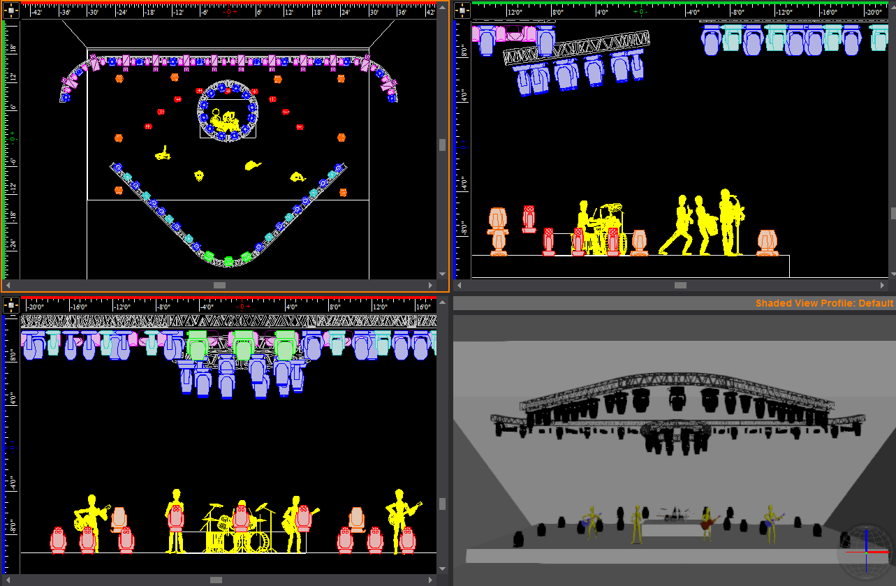
The Ruler dynamically updates as you zoom in and out. When you zoom in on your drawing, the precision of the ruler increases, displaying fractions and decimals; when you zoom out, the precision decreases to the point where both the grid and ruler disappear. The ruler matches the unit type currently set in your file, either Metric or Imperial. When working with larger venues, it is recommended that you increase the grid spacing so that the ruler will be visible when zoomed out further. The ruler matches the unit type.
The Ruler displays values with the negative sign to the left of 0’0” when in Plan, Front and Right view, or to the right of 0’0” when in Back and Left view.
On the Quad tab (as shown above), each of the three drawing quadrants can have a different drawing origin, or View Origin. When you define a new view origin, you can move the zero position of the ruler (-0 0+) to correspond to this point.
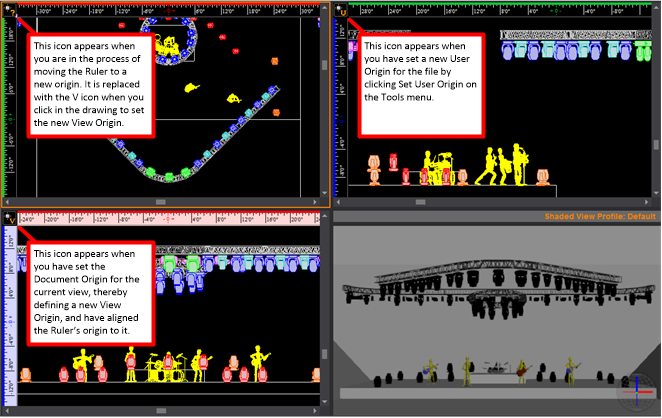
Based on the origin in the active quadrant and the corresponding position of the Ruler, the icon in the upper left corner of the Ruler changes.
Icon |
Description |
|---|---|
|
The Ruler’s zero position (origin) is aligned with the Document Origin, which is set by default to be the center point of the WYSIWYG venue defined for the event. |
|
By default, all views are set to the Document Origin. However, you can set the origin for each view, thereby defining a View Origin. This icon appears when you have defined a View Origin for the current view and have aligned the Ruler’s origin to it. |
|
This icon appears when you have set a new User Origin for the file by clicking Tools > Set User Origin. |
|
This icon appears when you have clicked Move Ruler (Set View Origin) from the Ruler menu and are in the process of defining your new origin. |
The following graphic shows a Quad tab in which the Ruler origin is different in each view:
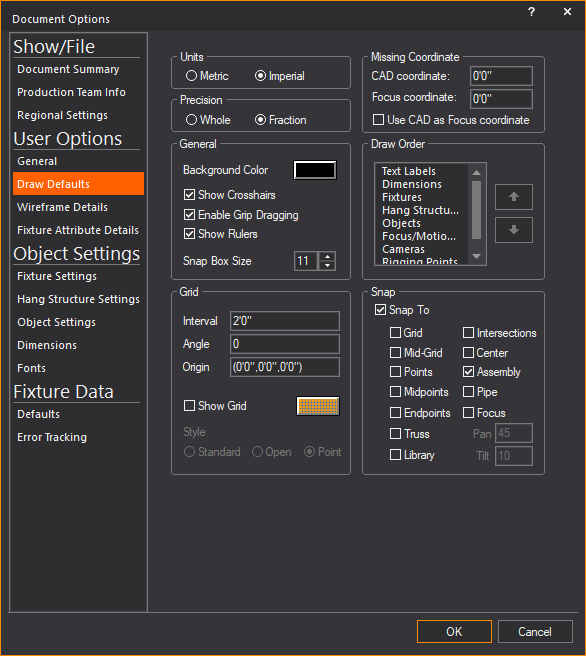
By default, the Ruler is turned On when you open a new WYSIWYG file. You can turn the ruler on and off while working in your file by using the Toggle Rulers icon on the CAD Options toolbar.
 The
Toggle Rulers button.
The
Toggle Rulers button.
Result: The Ruler appears or disappears.
Note: You can also toggle the ruler on or off by using the Draw Defaults tab in Document Options. Click Options > Document Options > Draw Defaults.
You can change the appearance of the ruler. The ruler can be white, the view color or the view color with a boarder.
Result: The Application Options window appears.
Result: The ruler’s appearance changes to that of the selected style.
By default, the ruler is aligned with the document origin, which means that the zero mark (-0 0+) starts at the Document Origin. However, you can move the Ruler from this default position to the origin of the current view. Note that doing so does not affect the origin or ruler of any other view.
Note: By moving the ruler, you are indirectly setting a new origin for the currently selected view. You can also change the Origin in a CAD view’s View Options > Draw Options tab, or by clicking Tools > Set User Origin.
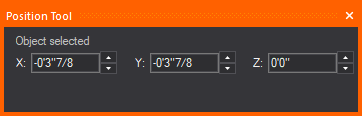
The Position Tool helps you determine the position of your selected object or objects in the Wireframe views of CAD mode, providing the precise coordinate reference numbers for the X, Y and Z axes.
The Position Tool can be used to change the position of your selected object or objects by specifying new coordinate numbers for the X, Y and Z axes.
The Position Tool window is dockable with a grab bar on top which can be used to move around the screen. You can place it on the edges of the work area or you can drag it off the edge, to become its own window and stay on top of the WYSIWYG screen. WYSIWYG opens with the Position Tool window open and docked above the Layer Database window by default.
Result: The Position Tool window appears showing the selected object’s X, Y and Z position coordinates in the drawing.
OR
On the Position Tool window, you may click the X, Y or Z boxes and type the numbers.
Result: The position of the selected object(s) changes according to the new coordinate reference numbers.
Notes:
You can open the Position Tool using the following shortcuts:
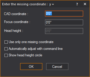
The missing coordinate (X,Y,or Z) is the coordinate whose value cannot be entered by clicking on the screen. The easy way to determine which coordinate is the missing coordinate in a wireframe view is to move the mouse around. Look at the Status bar at the bottom of the working area. You will see only two values changing. The value that is not changing is the missing coordinate for that view or workplane. The missing coordinate is dependent on the plot type and the workplane selected. In the following example, Y is the missing coordinate as its value is set at 0’0”.

Once entered, this value affects all subsequent objects inserted in the current view. For example, if the missing coordinate is set to 5’ in a plan view, all objects are placed 5 feet off the floor (X,Y,5) until the missing coordinate is changed again. Please note that the missing coordinate is not a move tool. Objects will not be moved to the missing coordinate value. The missing coordinate only affects subsequent inserts.
 The Missing Coordinate button.
Note: This box is enabled when the Show head height circle checkbox is selected.
Example:
a.Change to the plan view in your drawing.
b.Use TAB, and then type a value of “0" for the missing CAD coordinate.
c.Insert a few objects on the stage. All of these objects are drawn resting on the stage.
d.Change the missing CAD coordinate to a height of 10’.
e.Insert a riser by clicking the Riser button on the toolbar.
f.Although we are in a plan view the riser has been drawn at the height of 10', as specified in the missing coordinate dialog box.
g.Change to a side view and you will see that the riser has been placed above the stage.
Tip: If you select the Show head height circle checkbox, and then type a value in the Head height box, all subsequently focused fixture’s beams will display both the coverage at the specified head height, as well as the footprint of the beam on the surface below.
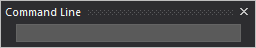
The Command Line is an area in WYSIWYG where you can enter coordinates for the purpose of placing or editing objects in a document. The placement of objects can often be done quicker and with more precision using the Command Line.
Generally, coordinates are specified as X, Y, Z. You can, however, insert coordinates using either two or three values. When using two values, the third value will be assumed from the missing coordinate. For details, refer to The missing coordinate.
The values that you specify in imperial mode are assumed to be in feet unless otherwise specified. Similarly, the values that you specify in metric mode are assumed to be in metres unless otherwise specified. At any time, you can specify values in both imperial and metric measurements (for example, 5”, 3 cm, 6’).
The following example illustrates the many different ways of using the Command Line.
Result: When you start typing, the Command Line toolbar appears.
Result: A new line segment is drawn and it assumes Z from the missing coordinate.
Result: A new line segment is drawn.
Result: A new line segment is drawn.
All objects occupy three-dimensional space. Different plot view types allow you to see and work with your drawing from different perspectives.
There are six types of plot views accessible from the CAD Options toolbar. The following definitions identify the working axes X, Y, and Z and the missing coordinate for each plot type. The missing coordinate can be defined as the axis for which a value cannot be set simply by clicking on the work space. For details, see The missing coordinate.
 Plan
View
Plan
ViewPlan views display the plot from above looking down. This is similar to a plan view drawing on paper. In plan views the working axes are X and Y and the missing coordinate is Z.
 Left View
Left views display the plot looking from the left side through the venue. This is similar to a section on paper. In left views the working axes are Y and Z and the missing coordinate is X.
 Right
View
Right
ViewRight views display the plot looking from the right side through the venue. This is similar to a section on paper. In right views the working axes are Y and Z and the missing coordinate is X.
 Front
View
Front
ViewFront views display the plot looking from the front side through the venue. This is similar to an elevation on paper. In front views the working axes are X and Z and the missing coordinate is Y.
 Back
View
Back
ViewBack views display the plot looking from the back side through the venue. This is similar to an elevation on paper. In back views the working axes are X and Z and the missing coordinate is Y.
 Isometric
View
Isometric
ViewAn Isometric view is a 3D perspective drawing. Despite this, you are still limited to two working axes. In isometric views, the working axes and the missing coordinate are dependent on the workplane selected. The workplanes available are:
 Workplane Selection
 Workplane Elevation
If a plan workplane is selected, the working axes are X and Y and the missing coordinate is Z.
If a side workplane is selected, the working axes are Y and Z and the missing coordinate is X.
If a front workplane is selected, the working axes are X and Z and the missing coordinate is Y.
The crosshairs of your cursor change to reflect the selected workplane.
Note: Isometric views are not available in WYSIWYG Report.
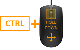
You can rotate the isometric angle of the Isometric View using your keyboard CTRL and arrow keys or CTRL keys and the third mouse button.
When using your mouse, you can also change the rotation speed when you increase or decrease the amount of pixels your mouse needs to travel to rotate the view on the screen using the CTRL keyboard and + or - keys in the keypad.
Hold down the CTRL key and tap the arrow keys on your keyboard.
or
Hold down the CTRL key, and then click and drag the third mouse button (scroll wheel) towards the direction of the angle change.
Result: The isometric angle of the Isometric View changes according to the direction of the mouse movement.
Tip: If you add SHIFT to either method, the rotation slows down for both keyboard and mouse movement.
Notes:
Press and hold CTRL + SHIFT and tap the + keypad key (i.e. not the + at the top of the keyboard, by the DELETE key) to increase the number of pixels your mouse cursor needs to travel to rotate the view on your screen and slow down the view rotation.
or
Press and hold CTRL + SHIFT and tap the - keypad key (i.e. not the - at the top of the keyboard, by the DELETE key) to decrease the number of pixels your mouse cursor needs to travel to rotate the view on your screen and speed up the view rotation.
Result:
The number of pixels value is displayed on the Status Bar as you increase or decrease with your keyboard keys.
It is faster for your mouse cursor to rotate the view when the travel distance is shorter because of the lesser amount of pixels set.
It is slower for your mouse cursor to rotate the view when the travel distance is longer because of the greater amount of pixels set.
Note: The default amount of mouse cursor travel distance in pixels is 20.
Ortho mode constrains your mouse movement and drawing to a direction parallel to the specified axis.
The view type determines the possible axes of movement; XY for plan views, YZ for side views, XZ for front and back views.
When ortho mode is inactive, objects can be drawn or moved in any direction on the workplane. You can draw diagonal lines or move objects anywhere in the working area.
From the Tools menu, choose Ortho and then the axis for the allowed movement.
or
You can activate Ortho mode at any time by clicking the ortho tools on the CAD Options toolbar or by right-clicking the Ortho label on the Status bar.
or
You can also use F8 on the keyboard or double-click the Ortho label on the Status bar to enable Ortho or to toggle your last recorded Ortho setting on or off.
|
X-Axis: Allows movement in the X - direction. |
|
Y-Axis: Allows movement in the Y - direction. |
|
Z-Axis: Allows movement in the Z - direction. |
Example: To choose the XY axis, click the X and Y buttons.
From your keyboard, you can use Alt + F8 to enable Ortho mode for only one axis of the current view or workplane.
Snaps are used to assist in the drawing and placement of objects. When a snap setting is active, the cursor will be drawn to the applicable snap point. You can have multiple snaps active at the same time. Snap selections can be made on the CAD Options toolbar or from the Tools menu.
All snap tools function as follows: If no command is currently active, you can adjust the running snap tool. This means that the snap type is always active. If you are in mid-command and you select a snap tool, it becomes a “one time only” snap type. After the next click, the snap returns to the running snap. At any time you can toggle all snaps on or off by using F9 or double-clicking on the SNAP text in the Status bar.
 Grid snap
Aligns the placement of objects to grid points. You can set the grid interval and angle in the Draw Options page of the View Options window.
 Mid-grid snap
Aligns the placement of objects between grid points.
 Point snap
Aligns the placement of objects to a point in the drawing. Fixture insertion points are considered points. It is therefore possible, using the Point snap, to align the placement of objects to fixtures (snap to fixtures). This is useful for dimensioning.
 Midpoint snap
Aligns the placement of objects to the mid-point of a line, arc, or any other object.
 Endpoint snap
Aligns the placement of objects to the end-points of a line, arc, pipe, or any other object.
 Intersection snap
Aligns the placement of objects to the intersection of lines, circles, or arcs on the same plane.
 Center snap
Aligns the placement of objects to the center-point of circles, arcs, or cylinders.
Aligns the placement of objects to the volumetric center-point of risers and spheres.
![]() Library
snap
Library
snap
Library Snap displays snap points at the bounding box corners of the library item, and one corner is displayed in red or green to indicate the library item’s insertion point, which aligns the placement of the item in the drawing. The snap point is displayed in red if the object is not selected or green if the object is selected. Refer to Library snap for more details.
 Truss snap
Truss Snap displays snap points at the extents of the truss objects (incorporating truss thickness if enabled) to help draw dimensions to measure the truss. Refer to Truss snap for more details.
 Truss Assembly snap
Use assembly snap to group multiple truss objects together as you insert them. This ensures proper structural assembly. Refer to Using assembly snap with truss for more details about truss assembly.
Constrains fixtures to placement on a pipe at a specific interval. Refer to Pipe snap for more details.
Orients one or more fixtures to a focus position. When you choose this value, you can also lock beam dragging to the incremental values of your choice, as specified in the Pan and Tilt boxes of the Draw Options tab (the defaults are increments of 45 degrees for pan and increments of 10 degrees for tilt). These are the values to which you want the fixture's beam to “snap” while manually dragging and focusing it. For example, if you set a value of 30 degrees, when you drag the fixture's beam, it will snap at 30 degrees, 60 degrees, 90 degrees, and so on. Note that any focus positions that you have set take precedence over the pan and tilt values (if you drag the beam over the focus position, it will automatically snap to the focus position instead).
Insertion points are pre-defined snap points on a 2D/3D primitive object or Library object that are used as insertion grips when placing objects into your drawing. The insertion point is identified by a red square snap point or grip.
This feature allows you to choose the Insertion Point from a list of pre-defined Insertion Points. Drawn objects or Library objects use a default insertion point. When you choose a different Insertion Point, the object will shift around the cursor, to the specified Insertion Point. The object will automatically use the same Insertion Point that was previously selected until changed.
Insertion Points for Library objects will only display if Library Snap is enabled. See Library snap in the Library Browser section for details.
Result: Your cursor snaps to the default insertion point of the object.
Result: Your cursor switches to the selected insertion point.
See Library snap in the Library Browser section.
You can change the insertion point of a single 2D/3D primitive object in your drawing to another insertion point. You can select only one 2D/3D primitive object to change its insertion point. You can change the insertion points of rectangles, arcs, elliptical arcs, polygons, risers, cylinders, cones, spheres, walls, screens, and LED walls.
Tip: You can right-click on the selected object, choose Change Insertion Point, and click on the new insertion point from the menu list of insertion points.
Result: The insertion point of the selected object moves to the new location.
Interactive mode is an alternative method for drawing objects. Objects are typically drawn using a dialog box to set the object’s size (width, depth, and height, for example). The full-size object is then attached to the cursor so you can place it in the drawing.
An Interactive button enables you to switch modes. Interactive mode allows you to click an insertion point for the object first, and then drag to create the scope of the object as allowed by the view (XY for plan view, XZ for front view, and so on).
Once those dimensions are set, a dialog box may open to allow you to set the third dimension, if required. Interactive mode works with Risers, Cylinders, Circles, Arcs, Spheres, and Pipes. There are some special considerations when drawing pipes in interactive mode, as explained in Drawing pipes.
Use F11 on your keyboard or click the Interactive tool on the CAD Options toolbar.
![]() © CAST Group of Companies Inc., 2002-2022
All rights reserved.
© CAST Group of Companies Inc., 2002-2022
All rights reserved.


 Workplane Plan
