
The Set User Origin button.
CAD mode - Creating Objects
CAD mode is where you create your show drawings. This includes drawing your venue, set pieces, lighting positions, focus positions, and lighting fixtures. CAD mode operates like many other CAD programs, so many of the concepts will be familiar to those who have used a computer-aided drafting program before. WYSIWYG adds features that are specific to the entertainment industry, such as a comprehensive 3D library containing truss, lighting equipment, lighting accessories, props, musical instruments, and various human figures.
In this section
Beneath the work area in each mode is a series of Layout tabs. These layouts provide various configurations of the views you are working with. To change layouts, click the tab that corresponds to the layout you wish to use.
The CAD mode contains the following layouts:
nWireframe: The work area displays a full-screen Wireframe view.
nQuad: The work area is divided into quadrants, three of which can be modified to show Plan, Front, Side, or Isometric Wireframe views. The lower-right quadrant contains a Shaded view.
nFlight Case: The Flight Case is displayed in a section of the work area along with a Wireframe view.
nShaded: The work area displays a full-screen Shaded view.
nCustom: A custom layout, with views defined by the user. See “Custom tab window layout”.
When drawing in WYSIWYG, you are drawing in real scale (1:1). When you create a drawing in CAD, you are generating a virtual representation of your real set-up. If you were to do this on paper by hand, you would need to draw a scaled-down version of your space. However, since there are no paper size limitations in CAD mode, you can draw your venue, sets, pipes, trusses, and lighting fixtures in real scale.
Scaling down for printing purposes is done during print set-up and in the Presentation (PRES) mode when creating plots. These settings allow you to print your drawings in whatever scales are necessary without having to redraw anything.
When working in CAD, you are working in a 3D environment (even in WYSIWYG Report). Objects are drawn as 3D objects, with width, depth, and height values using the Cartesian coordinate system of 3 working axes X, Y, and Z. The point where the 3 axes meet is called the origin and the value of X, Y, and Z is 0 respectively (0,0,0).
By default, the origin is set at the center point of the WYSIWYG venue that you insert. Inserting venues is discussed in “Drawing a venue”. You can reset the origin to another point in your drawing; you can set a user origin so that a different point will assume the values (0,0,0).
To set the user origin
1From the Tools menu, choose Set User Origin.
Tip: You can also use the Set User Origin tool on the Tools toolbar.
|
The Set User Origin button. |
2Click a point on your drawing or type in the coordinates (X,Y,Z) that will assume the values 0,0,0. This point will remain 0,0,0 until you change it again.
To reset the user origin
From the Tools menu, choose Reset User Origin.
Result: This resets the origin back to the WYSIWYG default.
When entering coordinates in WYSIWYG, you can specify a location or distance in either inch fractions (to the sixteenth of an inch) or millimeters. For example, you can specify a measurement of 1’6”3/16, which translates to 1 foot, 6 and 3/16 inches.
To set default options
1From the Options menu, choose Document Options.
2Click the Draw Defaults tab.
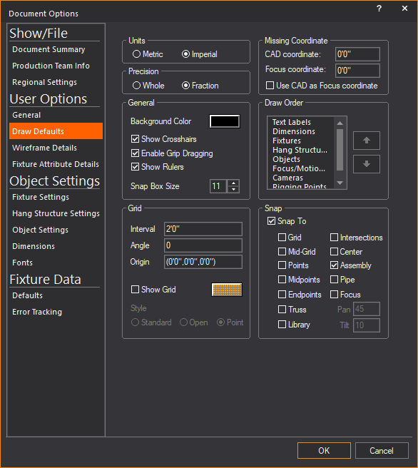
3Based on your choice for measurement in the Units section, you can choose to display the drawing resolution in whole numbers, fractions, centimeters, or millimeters.
nWhole: (Only visible if you choose Imperial units.) Indicates that the measurements are rounded and displayed to the nearest whole number.
nFraction: Indicates that the measurements are displayed to the nearest sixteenths of an inch.
ncm: (Only visible if you choose Metric units.) Indicates that the measurements are displayed in centimeters.
nmm: Indicates that the measurements are displayed in millimeters.
4Click OK.
WYSIWYG enables you to use metric or imperial units at any time. You may choose to set a default type of unit, and you may choose to switch unit type on the fly.
You can also indicate whether you want these units measured in whole numbers, fractions (to the sixteenth of a inch), centimeters, or millimeters.
To set the default unit type
1From the Options menu, choose Document Options.
2Click the Draw Defaults tab.
3Click either Metric or Imperial.
4Click either Whole, Fraction, mm or cm.
Note: These choices vary based on whether you selected Metric or Imperial in step 3.
To switch unit types on the fly
Double-click the units display on the Status bar.
The Ruler tool helps you design your show file in the Wireframe views of the CAD mode, providing a visual aid for coordinate reference and measurement. By default, the Ruler is aligned with the document origin and displays coordinate information along the top and left side of the view. Its scale matches the default grid scale.
As shown in the graphic below, the Ruler has different colors to represent different axes (X=Red, Y=Green, Z=Blue).

The Ruler dynamically updates as you zoom in and out. When you zoom in on your drawing, the precision of the ruler increases, displaying fractions and decimals; when you zoom out, the precision decreases to the point where both the grid and ruler disappear. The ruler matches the unit type currently set in your file, either Metric or Imperial. When working with larger venues, it is recommended that you increase the grid spacing so that the ruler will be visible when zoomed out further. The ruler matches the unit type.
The Ruler displays values with the negative sign to the left of 0’0” when in Plan, Front and Right view, or to the right of 0’0” when in Back and Left view.
On the Quad tab (as shown above), each of the three drawing quadrants can have a different drawing origin, or View Origin. When you define a new view origin, you can move the zero position of the ruler (-0 0+) to correspond to this point.
Based on the origin in the active quadrant and the corresponding position of the Ruler, the icon in the upper left corner of the Ruler changes.
Icon |
Description |
|---|---|
|
The Ruler’s zero position (origin) is aligned with the Document Origin, which is set by default to be the center point of the WYSIWYG venue defined for the event. |
|
By default, all views are set to the Document Origin. However, you can set the origin for each view, thereby defining a View Origin. This icon appears when you have defined a View Origin for the current view and have aligned the Ruler’s origin to it. |
|
This icon appears when you have set a new User Origin for the file by clicking Tools > Set User Origin. |
|
This icon appears when you have clicked Move Ruler (Set View Origin) from the Ruler menu and are in the process of defining your new origin. |
The following graphic shows a Quad tab in which the Ruler origin is different in each view:

By default, the Ruler is turned On when you open a new WYSIWYG file. You can turn the ruler on and off while working in your file by using the Toggle Rulers icon on the CAD Options toolbar.
1To show the CAD Options toolbar, right-click on the toolbars area and click CAD Options.
2On the CAD Options toolbar, click the Toggle Rulers icon.
|
The Toggle Rulers button. |
Result: The Ruler appears or disappears.
Note: You can also toggle the ruler on or off by using the Draw Defaults tab in Document Options. Click Options > Document Options > Draw Defaults.
a.To turn the Ruler off, clear the Show Rulers checkbox.
b.To turn the Ruler on, select in the Show Rulers checkbox.
3Click OK.
To change the ruler’s style
You can change the appearance of the ruler. The ruler can be white, the view color or the view color with a boarder.
1In CAD mode, from the Options menu, choose Application Options.
Result: The Application Options window appears.
2In the Application Options window, select the desired ruler style from the Ruler Style drop-down list.
3Click OK.
Result: The ruler’s appearance changes to that of the selected style.
By default, the ruler is aligned with the document origin, which means that the zero mark (-0 0+) starts at the Document Origin. However, you can move the Ruler from this default position to the origin of the current view. Note that doing so does not affect the origin or ruler of any other view.
1In the Quad tab, click the quadrant in which you want to move the Ruler.
2Click the icon in the upper left corner of the Ruler (or right-click on the actual Ruler) and select one of the following options:
nDisplay Ruler at Document Origin: Select this option to realign the Ruler’s zero point with the Document Origin, which is set by default to be the origin of the WYSIWYG file. When the ruler is displayed at the Document/User origin, the background color of the ruler follows the selected Ruler Style option in the General tab of Application Options.
nDisplay Ruler at View Origin: Select this option if you want to realign the Ruler to the View Origin of the current view, if different than the original Document Origin. To indicate this change, the background of the Ruler changes to match the axis colors.
nMove Ruler (Set View Origin): Select this option if you want to choose a new origin for the ruler. Then click the cursor on the point in your drawing that you want to designate as the zero mark for the Ruler. Once the Ruler is moved, you can use the previous two menu items (Display Ruler at Document Origin and Display Ruler at View Origin) to switch the ruler’s position from the default position to the user defined position.
Note: By moving the ruler, you are indirectly setting a new origin for the currently selected view. You can also change the Origin in a CAD view’s View Options > Draw Options tab, or by clicking Tools > Set User Origin.
The Position Tool helps you determine the position of your selected object or objects in the Wireframe views of CAD mode, providing the precise coordinate reference numbers for the X, Y and Z axes.
The Position Tool can be used to change the position of your selected object or objects by specifying new coordinate numbers for the X, Y and Z axes.
The Position Tool window is dockable with a grab bar on top which can be used to move around the screen. You can place it on the edges of the work area or you can drag it off the edge, to become its own window and stay on top of the WYSIWYG screen. WYSIWYG opens with the Position Tool window open and docked above the Layer Database window by default.
To use the position tool
1Select an object in wireframe view.
2From the View menu, choose Position Tool.
Result: The Position Tool window appears showing the selected object’s X, Y and Z position coordinates in the drawing.

3On the Position Tool window, click the X, Y or Z scroll box arrows to increase or decrease the reference coordinate numbers.
OR
On the Position Tool window, you may click the X, Y or Z boxes and type the numbers.
Result: The position of the selected object(s) changes according to the new coordinate reference numbers.
Notes:
nYou can select more than one object and you can move more than one object.
nIf multiple objects are selected and arrow buttons are used, the objects move to relative positions.
nIf multiple objects are selected and a coordinate value for an axis is entered, the objects move to the same position. For example, if multiple objects are selected and you entered a coordinate value in the Z axis box, the objects move to the same Z axis coordinate.
nThe increment/decrement size is equal to the Grid Interval property in Document Options > Draw Defaults tab.
Position Tool shortcuts
You can open the Position Tool using the following shortcuts:
nCTRL+ALT+P: Opens the Position Tool window.
nCTRL+SHIFT+X: With an object(s) selected, opens the Position Tool window and the cursor in X.
nCTRL+SHIFT+Y: With an object(s) selected, opens the Position Tool window and the cursor in Y.
nCTRL+SHIFT+Z: With an object(s) selected, opens the Position Tool window and the cursor in Z.
The missing coordinate (X,Y,or Z) is the coordinate whose value cannot be entered by clicking on the screen. The easy way to determine which coordinate is the missing coordinate in a wireframe view is to move the mouse around. Look at the Status bar at the bottom of the working area. You will see only two values changing. The value that is not changing is the missing coordinate for that view or workplane. The missing coordinate is dependent on the plot type and the workplane selected. In the following example, Y is the missing coordinate as its value is set at 0’0”.

Once entered, this value affects all subsequent objects inserted in the current view. For example, if the missing coordinate is set to 5’ in a plan view, all objects are placed 5 feet off the floor (X,Y,5) until the missing coordinate is changed again. Please note that the missing coordinate is not a move tool. Objects will not be moved to the missing coordinate value. The missing coordinate only affects subsequent inserts.
To enter a value for the missing coordinate
1Use TAB on your keyboard or click the Missing Coordinate tool on the CAD Options toolbar.
|
The Missing Coordinate button. |

2In the CAD coordinate box, type the value for the CAD coordinate.
3The Focus Coordinate tells WYSIWYG where to place the cursor (i.e., at which missing coordinate) when manually focusing fixtures. If you type any value other than 0 in this box, you will notice that the beam's centreline extends past the crosshairs when you drag the beam around with your mouse. This represents the distance between the Focus Coordinate and the floor (or whatever is stopping the beam).
4If you want to use only the CAD coordinate for focusing and placing/editing objects, select the Use only one missing coordinate checkbox.
5To automatically adjust the missing coordinate with any 3D coordinate value that you enter on the Command Line, select the Automatically adjust with Command Line checkbox.
6Select the Show head height checkbox to display the coverage of beams at the head height selected in the Head height box.
7In the Head height box, type a value to check the light coverage at a certain height (the height of the performer).
Note: This box is enabled when the Show head height circle checkbox is selected.
8When you are finished with your selections, click OK.
Example:
a.Change to the plan view in your drawing.
b.Use TAB, and then type a value of “0" for the missing CAD coordinate.
c.Insert a few objects on the stage. All of these objects are drawn resting on the stage.
d.Change the missing CAD coordinate to a height of 10’.
e.Insert a riser by clicking the Riser button on the toolbar.
f.Although we are in a plan view the riser has been drawn at the height of 10', as specified in the missing coordinate dialog box.
g.Change to a side view and you will see that the riser has been placed above the stage.
Tip: If you select the Show head height circle checkbox, and then type a value in the Head height box, all subsequently focused fixture’s beams will display both the coverage at the specified head height, as well as the footprint of the beam on the surface below.
The Command Line is an area in WYSIWYG where you can enter coordinates for the purpose of placing or editing objects in a document. The placement of objects can often be done quicker and with more precision using the Command Line.
Generally, coordinates are specified as X, Y, Z. You can, however, insert coordinates using either two or three values. When using two values, the third value will be assumed from the missing coordinate. For details, refer to “The missing coordinate”.
The values that you specify in imperial mode are assumed to be in feet unless otherwise specified. Similarly, the values that you specify in metric mode are assumed to be in metres unless otherwise specified. At any time, you can specify values in both imperial and metric measurements (for example, 5”, 3 cm, 6’).
The following example illustrates the many different ways of using the Command Line.
1In a plan view, from the Draw menu, choose Line.
2From the sub-menu, choose Solid, Dot, Center, Hidden or Spline.
3Type 0,0 as the starting point of the line.
Result: When you start typing, the Command Line toolbar appears.
4Use ENTER to establish the first point of the line at the origin.
5To set the next point at exactly X=5 and Y=5, type 5,5, and then use ENTER.
Result: A new line segment is drawn and it assumes Z from the missing coordinate.
6To place the next point of the line 10 units to the right and 5 units up (in Y) from the last point, type @10,5, and then use ENTER.
Result: A new line segment is drawn.
7To place the next point at exactly 5 feet, 3 metres, and 6 inches from the last point, type 5’, 3m, 6”, and then use ENTER.
Result: A new line segment is drawn.
8When you are finished drawing the lines, right-click, and then select Finish Line.
All objects occupy three-dimensional space. Different plot view types allow you to see and work with your drawing from different perspectives.
There are six types of plot views accessible from the CAD Options toolbar. The following definitions identify the working axes X, Y, and Z and the missing coordinate for each plot type. The missing coordinate can be defined as the axis for which a value cannot be set simply by clicking on the work space. For details, see “The missing coordinate”.
Plan views display the plot from above looking down. This is similar to a plan view drawing on paper. In plan views the working axes are X and Y and the missing coordinate is Z.
Left views display the plot looking from the left side through the venue. This is similar to a section on paper. In left views the working axes are Y and Z and the missing coordinate is X.
Right views display the plot looking from the right side through the venue. This is similar to a section on paper. In right views the working axes are Y and Z and the missing coordinate is X.
Front views display the plot looking from the front side through the venue. This is similar to an elevation on paper. In front views the working axes are X and Z and the missing coordinate is Y.
Back views display the plot looking from the back side through the venue. This is similar to an elevation on paper. In back views the working axes are X and Z and the missing coordinate is Y.
An Isometric view is a 3D perspective drawing. Despite this, you are still limited to two working axes. In isometric views, the working axes and the missing coordinate are dependent on the workplane selected. The workplanes available are:
n Workplane Selection
n Workplane Elevation
If a plan workplane is selected, the working axes are X and Y and the missing coordinate is Z.
If a side workplane is selected, the working axes are Y and Z and the missing coordinate is X.
If a front workplane is selected, the working axes are X and Z and the missing coordinate is Y.
The crosshairs of your cursor change to reflect the selected workplane.
Note: Isometric views are not available in WYSIWYG Report.
You can rotate the isometric angle of the Isometric View using your keyboard CTRL and arrow keys or CTRL keys and the third mouse button.
When using your mouse, you can also change the rotation speed when you increase or decrease the amount of pixels your mouse needs to travel to rotate the view on the screen using the CTRL keyboard and + or - keys in the keypad.
To rotate the isometric angle
Hold down the CTRL key and tap the arrow keys on your keyboard.
OR
Hold down the CTRL key, and then click and drag the third mouse button (scroll wheel) towards the direction of the angle change.

Result: The isometric angle of the Isometric View changes according to the direction of the mouse movement.
Tip: If you add SHIFT to either method, the rotation slows down for both keyboard and mouse movement.
Notes:
nRotation direction is determined by the dominant direction of mouse movement. For example, the view rotates in the left-right angle if the mouse is dragged towards the left and slightly up. The view rotates in the up-down angle if the mouse is dragged upwards and slightly left.
nOnce the rotation direction has been determined and the rotation has started, the rotation cannot “switch” to the other direction. You have to release the mouse button and then click and drag again.
To change the mouse cursor speed and travel distance
Press and hold CTRL + SHIFT and tap the + keypad key (i.e. not the + at the top of the keyboard, by the DELETE key) to increase the number of pixels your mouse cursor needs to travel to rotate the view on your screen and slow down the view rotation.
OR
Press and hold CTRL + SHIFT and tap the - keypad key (i.e. not the - at the top of the keyboard, by the DELETE key) to decrease the number of pixels your mouse cursor needs to travel to rotate the view on your screen and speed up the view rotation.
Result:
The number of pixels value is displayed on the Status Bar as you increase or decrease with your keyboard keys.
It is faster for your mouse cursor to rotate the view when the travel distance is shorter because of the lesser amount of pixels set.
It is slower for your mouse cursor to rotate the view when the travel distance is longer because of the greater amount of pixels set.
Note: The default amount of mouse cursor travel distance in pixels is 20.
Ortho mode constrains your mouse movement and drawing to a direction parallel to the specified axis.
The view type determines the possible axes of movement; XY for plan views, YZ for side views, XZ for front and back views.
When ortho mode is inactive, objects can be drawn or moved in any direction on the workplane. You can draw diagonal lines or move objects anywhere in the working area.
To activate ortho
From the Tools menu, choose Ortho and then the axis for the allowed movement.
OR
You can activate Ortho mode at any time by clicking the ortho tools on the CAD Options toolbar or by right-clicking the Ortho label on the Status bar.
OR
You can also use F8 on the keyboard or double-click the Ortho label on the Status bar to enable Ortho or to toggle your last recorded Ortho setting on or off.
|
X-Axis: Allows movement in the X - direction. |
|
Y-Axis: Allows movement in the Y - direction. |
|
Z-Axis: Allows movement in the Z - direction. |
To select or cancel the axes with toolbar buttons
1Click the appropriate two buttons to select both axes.
Example: To choose the XY axis, click the X and Y buttons.
To cancel and reset ortho buttons
1From your keyboard, use F8 to disable any ortho buttons that you have chosen.
2Use F8 again to reset the same ortho selection as that which was previously selected.
From your keyboard, you can use Alt + F8 to enable Ortho mode for only one axis of the current view or workplane.
To enable and disable single axis ortho
1Press Alt + F8 to enable the first axis of the current view or workplane regardless of the current Ortho state (i.e. both axis on or both axis off).
2Press Alt + F8 for the second time to disable the first Ortho axis and enable the second Ortho axis.
3From a single axis Ortho mode, press F8 once to disable the Ortho mode.
4From a single axis Ortho mode, press F8 twice in sequence to enable double axes Ortho mode.
Snaps are used to assist in the drawing and placement of objects. When a snap setting is active, the cursor will be drawn to the applicable snap point. You can have multiple snaps active at the same time. Snap selections can be made on the CAD Options toolbar or from the Tools menu.
All snap tools function as follows: If no command is currently active, you can adjust the running snap tool. This means that the snap type is always active. If you are in mid-command and you select a snap tool, it becomes a “one time only” snap type. After the next click, the snap returns to the running snap. At any time you can toggle all snaps on or off by using F9 or double-clicking on the SNAP text in the Status bar.
n Grid
snap
Grid
snap
Aligns the placement of objects to grid points. You can set the grid interval and angle in the Draw Options page of the View Options window.
n Mid-grid
snap
Mid-grid
snap
Aligns the placement of objects between grid points.
n Point
snap
Point
snap
Aligns the placement of objects to a point in the drawing.
Fixture insertion points are considered points. It is therefore possible, using the Point snap, to align the placement of objects to fixtures (snap to fixtures). This is useful for dimensioning.
n Midpoint
snap
Midpoint
snap
Aligns the placement of objects to the mid-point of another line.
n Endpoint
snap
Endpoint
snap
Aligns the placement of objects to the end-point of another line.
n Intersection
snap
Intersection
snap
Aligns the placement of objects to the intersection of lines, circles or arcs on the same plane.
n Center
snap
Center
snap
Aligns the placement of objects to the center-point of circles, arcs, or cylinders.
n![]() Library
snap
Library
snap
Library Snap displays snap points at the bounding box corners of the library item, and one corner is displayed in red or green to indicate the library item’s insertion point, which aligns the placement of the item in the drawing. The snap point is displayed in red if the object is not selected or green if the object is selected. Refer to “Library snap”for more details.
n Truss
snap
Truss
snap
Truss Snap displays snap points at the extents of the truss objects (incorporating truss thickness if enabled) to help draw dimensions to measure the truss. Refer to “Truss snap” for more details.
Use assembly snap to group multiple truss objects together as you insert them. This ensures proper structural assembly. Refer to “Using assembly snap with truss” for more details about truss assembly.
Constrains fixtures to placement on a pipe at a specific interval. Refer to “Pipe snap” for more details.
Orients one or more fixtures to a focus position. When you choose this value, you can also lock beam dragging to the incremental values of your choice, as specified in the Pan and Tilt boxes of the Draw Options tab (the defaults are increments of 45 degrees for pan and increments of 10 degrees for tilt). These are the values to which you want the fixture's beam to “snap” while manually dragging and focusing it. For example, if you set a value of 30 degrees, when you drag the fixture's beam, it will snap at 30 degrees, 60 degrees, 90 degrees, and so on. Note that any focus positions that you have set take precedence over the pan and tilt values (if you drag the beam over the focus position, it will automatically snap to the focus position instead).
Insertion points are pre-defined snap points on a 2D/3D primitive object or Library object that are used as insertion grips when placing objects into your drawing. The insertion point is identified by a red square snap point or grip.
This feature allows you to choose the Insertion Point from a list of pre-defined Insertion Points. Drawn objects or Library objects use a default insertion point. When you choose a different Insertion Point, the object will shift around the cursor, to the specified Insertion Point. The object will automatically use the same Insertion Point that was previously selected until changed.
Insertion Points for Library objects will only display if Library Snap is enabled. See “Library snap” in the Library Browser section for details.
To select the object’s insertion point
1Choose a 2D or 3D object to draw, or select an object from the Library.
2Set or change the object’s specifications in the settings dialog box that appears.
3Click OK.
Result: Your cursor snaps to the default insertion point of the object.
4Right-click the object to display the menu list of insertion points.
5Click on the new insertion point.
Result: Your cursor switches to the selected insertion point.
6Place the object into your drawing.
To select the library object’s insertion point
See “Library snap” in the Library Browser section.
You can change the insertion point of a single 2D/3D primitive object in your drawing to another insertion point. You can select only one 2D/3D primitive object to change its insertion point. You can change the insertion points of rectangles, arcs, elliptical arcs, polygons, risers, cylinders, cones, spheres, walls, screens, and LED walls.
To change the object’s insertion point
1Select a 2D or 3D object in your drawing.
2From the Edit menu, choose Change Insertion Point, and click on the new insertion point from the menu list of insertion points.
Tip: You can right-click on the selected object, choose Change Insertion Point, and click on the new insertion point from the menu list of insertion points.
Result: The insertion point of the selected object moves to the new location.
Interactive mode is an alternative method for drawing objects. Objects are typically drawn using a dialog box to set the object’s size (width, depth, and height, for example). The full-size object is then attached to the cursor so you can place it in the drawing.
An Interactive button enables you to switch modes. Interactive mode allows you to click an insertion point for the object first, and then drag to create the scope of the object as allowed by the view (XY for plan view, XZ for front view, and so on).
Once those dimensions are set, a dialog box may open to allow you to set the third dimension, if required. Interactive mode works with Risers, Cylinders, Circles, Arcs, Spheres, and Pipes. There are some special considerations when drawing pipes in interactive mode, as explained in “Drawing pipes”.
To set interactive as the default drawing mode
1From the Options menu, choose Document Options.
2Click the Object Settings tab.
3In the Drawing options section, select the Interactive object creation checkbox.
To set interactive mode on the fly
Use F11 on your keyboard or click the Interactive tool on the CAD Options toolbar.
My Virtual Rig or MVR is an open-file-format container that bundles a set of entities such as fixtures, hang structures, fully-textured sets, multimedia elements, fixture control information, and others into a single file which is compatible with a large number of consoles and other applications used in the entertainment industry. The MVR file format allows CAD software applications, visualizers, and consoles to exchange files easily.
Notes:
nFamiliarity with the MVR being imported will help you choose the type of Assets and which Layers to import. If you are not familiar with the MVR, it is best to proceed with the default selections from WYSIWYG. You can delete the imported entities that are not required after the import is complete.
nIt is strongly recommended for the fixtures within the MVR to be associated with GDTF Profiles, else it may not be possible to determine their operation mode, DMX footprint, and other options, which may make it impossible to correctly map incoming fixtures to their WYSIWYG counterparts.
Importing MVR files into WYSIWYG requires the conversion of MVR Nodes into equivalent WYSIWYG entities.
In WYSIWYG, from the Welcome Screen, you can import the MVR file from the Import section or choose to open a file from the Open section or File menu. Importing an MVR in WYSIWYG creates a new WYSIWYG document out of the MVR file.
The MVR Import Wizard appears after you select the MVR file from your browser window. The MVR Import Wizard provides information and import options for the MVR file you chose to import.
Converting MVR Nodes to WYSIWYG entities
The MVR-WYG Translation Table describes how MVR Nodes convert to WYSIWYG. MVR Nodes are referred to as Assets in The MVR Import Wizard.
MVR Node |
WYSIWYG Entity |
Notes |
|---|---|---|
Symdef |
Library Item |
Imports into the MVR folder in the main folder Library > Objects Library. |
Position |
Position |
Appears in the Position Manager. |
Layer |
Layer |
The option to choose which Layers to import appears in Step 1 of the MVR Import Wizard. |
SceneObject |
SetPiece or Library Item |
Objects in MVR files are stored in the .3DS file format, complete with textures. If only one instance of an object exists in the .MVR file, it imports as a Set Piece, whereas two or more import as Library Items. In most cases, either entity type will feature Elements which can be used to easily make changes to their textures. |
GroupObject |
Group |
In MVR or WYSIWYG, groups can be nested and one object can only belong to one group. In WYSIWYG, Fixtures cannot be grouped. Fixtures that belong to a group in MVR will be extracted from the group. |
FocusPoint |
Focus Position |
When FocusPoint Nodes exist in the MVR file and at least one fixture in the MVR file is linked to a FocusPoint, Focus Position Assets are forced to import. |
Fixture |
Fixture |
Incoming Fixtures must be mapped manually to the equivalent WYSIWYG Fixture (Library Profile). This is done in Step 2 of the MVR Import Wizard. Resulting fixtures retain the incoming fixtures’ attributes (layer, location in 3D space, hang position, patch, fixture ID, etc.). Unmapped Fixtures will import as Null (Dummy) fixtures, but these will retain all incoming attributes and may be replaced with actual fixtures from the WYSIWYG Library at any time, after the import completes. |
Truss |
Library Item |
Incoming Truss converts into a Library Item which retains the Name attribute from the MVR file. |
VideoScreen |
Screen |
The option to import Video Screens appears in Step 1 of the MVR Import Wizard. |
To import an mvr file
1On the Welcome Screen, click My Virtual Rig in the Import section.
Tip: You can open the MVR file from the Open section of the Welcome Screen or choose Open from the File menu.
Result: The Import browser window appears.
2In the browser, select and open the MVR file you want to import.
Result: The MVR Import Wizard appears.

The MVR Import Wizard consists of two steps:
nStep 1: File Information, Import Type, Assets and Layers Selection window is where you can select import options.
nStep 2: Fixture Mapping is where you select the fixtures to import and map them to their equivalent in WYSIWYG (Library profiles). The Fixture Mapping window only appears if you selected Fixtures for import.
The File Information section in Step 1 displays non-editable information about the MVR file you have selected to import.
nFilename: The name of the MVR file.
nCreated with: The name of the application used to save the MVR file with the internal version number (in brackets) provided by the application where the file originated.
nMVR Version: The MVR spec (specification) version used by the application in which the file was created.
3On the Import Type section, select the New Import option to specify that you will import the MVR file for the first time, and the import will consider everything contained in the MVR file.
Note: The Update Current File option cannot be selected in R46.
4On the Assets section, select which types of MVR Nodes contained in the MVR file will be imported.
The number within brackets beside each checkbox label indicates how many MVR Nodes (Assets) from each category are contained within the MVR file.
Assets
nFixtures [#]: The Fixture Nodes contained in the MVR file that you will import must be mapped to match the equivalent fixtures in the WYSIWYG Library Browser. You can map Fixtures on the Fixture Mapping table that appears in Step 2.
Each imported Fixture will hang from its own 10cm-long pipe.
nFocus Positions [#]: You must import FocusPoint Nodes to maintain focus of the Fixtures you are importing.
nIf the MVR file contains FocusPoint Nodes and at least one Fixture Node is linked to the FocusPoint and you have selected the Fixtures checkbox in the Assets section, the Focus Positions checkbox is automatically selected by default and grayed out (disabled). This will ensure that fixtures always import focused.
Important Note: Focus Positions will not import if they belong to Layer(s) that are not selected for import.
nHang Structures [#]: Truss Nodes contained in the MVR file such as truss, pipes, and other rigging structures do not convert to the actual WYSIWYG Truss or Pipes from which fixtures hang. Truss Nodes contained in the MVR file will import as Library Items and stored in the Objects Library > MVR folder.
nHang Structures imported as Library Items will not prevent immediate pre-cue or previz because the placement orientation of Fixtures included in the MVR import will be correct. (This is ensured by the fact that each imported fixture hangs from its own 10cm Pipe.)
Note: The Cast Shadow option is automatically disabled for any Library Item object that was converted from Truss Nodes.
nScreens [#]: VideoScreen Nodes contained in the MVR file such as projection screens, TV, and other screen-type objects do not convert to the actual WYSIWYG Screen objects. VideoScreen Nodes contained in the MVR file will import as Consolidated Mesh objects. The imported Screen object will retain the applied image.
nObjects [#]: SceneObject Nodes contained in the MVR file, such as scenery, furniture, etc., will import in WYSIWYG as Consolidated Mesh object or Library Item.
If a single instance of an Object is contained in the MVR file, the Object will import as a Consolidated Mesh object. If more than one instance of an Object is contained in the MVR file, the Objects will import as Library Items and stored in the Objects Library > MVR folder. WYSIWYG retains the full geometry and textures of imported Objects.
Note: Assets will only import if you import the Layers which contain them.
5On the Layers section, select which Layers contained in the MVR file will be imported. The Table in this section displays as many rows as the number of Layers in the MVR file and the following columns: Import, Status, Layer Name, Tag, and Description/Notes.
Tip: Click any of the column headers to sort the table by that column.
Layers
nImport: In the Import column, select the checkboxes of the corresponding rows to import the Layers. By default, all Layers’ Import checkboxes are selected unless their status displays 0.
nStatus: In the Status column, status icons provide basic information about the incoming Layers, or indicate which Layers require attention.
n : The “Empty” icon indicates that
the Layer does not contain Assets selected for import or contains no Assets
at all. It is recommended that such Layers’ Import checkbox
is not selected (unless you wish to import one or more empty Layers).
: The “Empty” icon indicates that
the Layer does not contain Assets selected for import or contains no Assets
at all. It is recommended that such Layers’ Import checkbox
is not selected (unless you wish to import one or more empty Layers).
n : The “New Layer” icon indicates
that this Layer will be added to the resulting .wyg
file.
: The “New Layer” icon indicates
that this Layer will be added to the resulting .wyg
file.
nLayer Name: The cells in the Layer Name column are pre-filled and not editable. WYSIWYG must retain the names of the Layers contained in the MVR file.
nBy default, this table is sorted by the Layer Name column.
nWhen you hover over a Layer’s name cell, the tooltip lists and counts the Asset types in that Layer.
nTag: Click and type on this cell to add a keyword for the selected Layer.
nDescription/Notes: Click and type on this cell to add text information for the selected Layer.
Tips:
nClick the Select All button and select or clear any Import checkbox to select all or clear all the Layers in the table at once. Click the Select None button to individually select or clear each Import checkbox.
nFewer than all Layers may be selected with CTRL+click or SHIFT+click.
6Click Next to proceed to Step 2: Fixture Mapping of the MVR Import Wizard.
If you are not importing Fixtures, click the Finish button. If this step doesn’t appear, go to Step 12 of this procedure section.
Result: The Step 2: Fixture Mapping window appears.
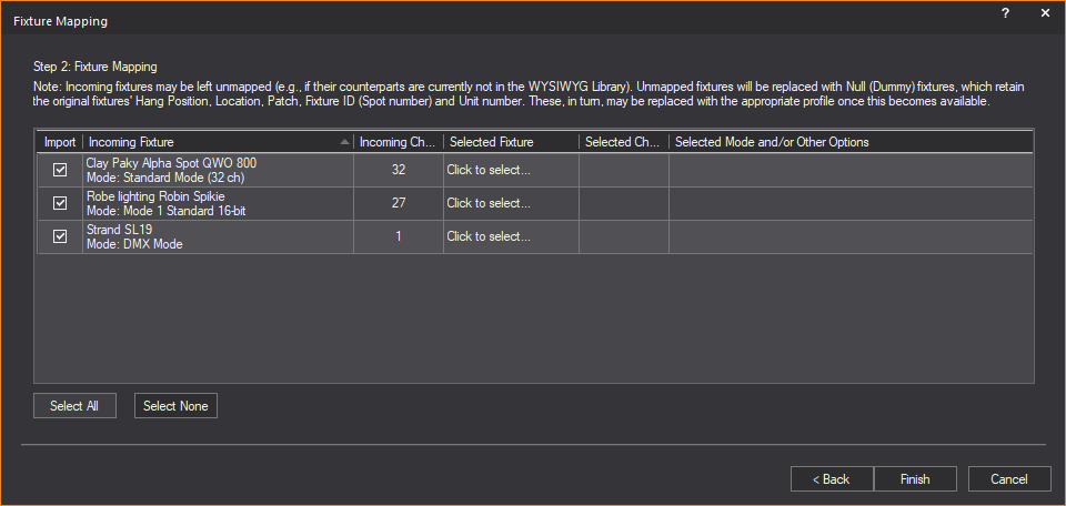
Step 2: Fixture Mapping window appears only if Fixtures Assets were selected for import.
Fixture Information and Mapping
In the Fixture Mapping table:
nYou can select which fixtures to import, and map them to their equivalents in WYSIWYG (Library profiles).
nAll the unique permutations of every fixture type contained in the MVR file are listed.
nOnly fixtures that belong to a Layer selected for import are listed.
nFixture information is displayed for accurate mapping.
The columns in the Fixture Mapping table:
nImport: Select the checkbox in this column to import this fixture. By default, all Layers’ Import checkboxes are selected.
nIncoming Fixture: The auto-filled cells in this column display the name and other information about the fixture as these appear in the MVR file. You can only sort the table list order by this column.
nIncoming Channels: The auto-filled cells in this column display the number of DMX channels required by the incoming fixture (based on its operation Mode and/or other options).
nSelected Fixture: Click the ellipsis button in the cells of this column to select the replacement fixture from the WYSIWYG Library Browser.
nSelected Channels: The auto-filled/editable cells in this column displays the number of DMX channels of the replacement fixture.
nSelected Mode and/or Other Options: The auto-filled/editable cells in this column display the fixture settings you selected in the Library Browser.
7In the Fixture Mapping table, select the Import checkbox of the Incoming Fixture you want to map.
Result: The selected row is highlighted.
8On the selected row, click on the cell under the Selected Fixture column and click the ellipsis button that appears.
Result: The modal Library Browser window appears.

9In the modal Library Browser, browse and choose the equivalent fixture that will replace the Incoming Fixture selected for import.
Tip:
nTo select the correct operation Mode and/or other options for the mapping fixture, click the Library Browser’s Options and Photometrics tabs; at the bottom-right of the Options tab, check the Number of Channels field in order to ensure that the operation mode and/or other options you selected above results in the same number of DMX channels for the mapped fixture as for the incoming fixture.
nWhen the modal Library Browser opens again subsequently, it can recall the previous search by clicking the Search field drop-down arrow.
nIf you select the Remember for future imports checkbox in the modal Library Browser, WYSIWYG will automatically map the same fixture that appears again in the next MVR file import. (You can change the automatic mapping if required.)
10In the modal Library Browser, click Insert.
Result:
nThe Library Browser closes.
nIn the Fixture Mapping table, the replacement fixture appears in the Selected Fixture cell, the number of DMX channels appears in the Selected Channels cell, and the fixture settings of the inserted fixture appear in the Selected Mode and/or Other Options cell.
nNull (Dummy) fixtures: If you did not find the equivalent fixture replacement, a Null (Dummy) fixture replaces the unmapped fixture with its original attributes retained. Such Null (Dummy) fixtures get a Note automatically, which states which fixtures from the MVR file they replaced. (This Note appears in their Properties > Fixture tab, as well as in their Notes cells in DATA Spreadsheets.
11Repeat Steps 7 to 10 for every Incoming Fixture you want to map.
Tip:
nClick the Select All button and select or clear any Import checkbox to select all or clear all the rows in the table at once. Click the Select None button to individually select or clear each Import checkbox.
nClick Back to go back to Step 1 or click Cancel to quit the import.
12On the Fixture Mapping window, click Finish.
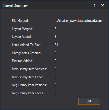
Result: The Import Summary window appears.
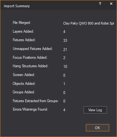
13Click OK.
Result: The MVR file is imported as a new WYSIWYG document.
For supplementary information on MVR Importing, see the “MVR importing notes” section.
SketchUp is a modeling tool that enables you to create realistic 3D models of many different types of objects and then save the files with an “.skp” extension. You can import these SketchUp files into WYSIWYG in much the same way as you import DWG/DXF files.
Before you import SketchUp files into WYSIWYG, note the following:
nWhile SketchUp supports two textures per surface, one each for the front and back, WYSIWYG supports only one texture for both sides of imported surfaces; when you are importing SketchUp files, WYSIWYG will automatically apply the front texture to both sides of the object.
nWYSIWYG supports “.skp” files from SketchUp version 2019 format and earlier at the time of this release.
When you import SketchUp files into WYSIWYG, the textures associated with these files are saved in a folder on your computer so you can apply them to imported surfaces. By saving them to a folder outside of WYSIWYG, you can use them repeatedly instead of only applying them to the surfaces that are within the current WYSIWYG document.
Upon import, you can choose the location for saving the associated texture files (or accept the default location). If there is already a texture with the same name saved in the location specified, WYSIWYG will prompt you to save the file with a new name.
When importing a SketchUp file into WYSIWYG, you have two options:
nYou can open a file.
nYou can merge a file into an existing WYSIWYG document.
If you open a SketchUp file while another show document is currently open, you are prompted to save changes to that document before another show document is opened. Only one show document may be open at a time. When you merge documents, you can add the contents of the SketchUp file to the contents of the current WYSIWYG document.
This procedure creates a new WYSIWYG document out of the SketchUp file, prompting you to save changes to any current document that is open and close it before importing the file.
Before you begin
You must have the SketchUp file saved on your computer to begin this procedure.
1From the File menu, choose Open.
2From the Files of type box, select SketchUp files (.skp), and then navigate to the location where the file is saved on your computer.
3In the browser, click the file name, and then click Open.
Result: The Import Directories window appears.
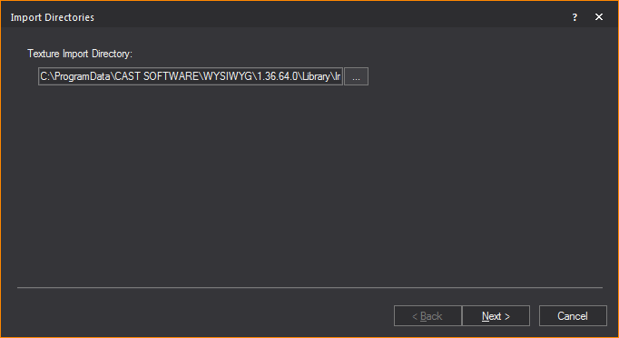
4Click the browse button to specify the location where you want to save the textures that have been applied to the object in SketchUp, or accept the default location shown. By saving textures to a folder outside of WYSIWYG, you can use them repeatedly instead of only applying them to the surfaces that are within the current WYSIWYG document.
Note: If a default path is not shown, you must click the browse button and navigate to the desired folder. If there is already a texture with the same name saved in the location specified, WYSIWYG will prompt you to save the file with a new name.
5Click Next.
Result: The Layer window appears.
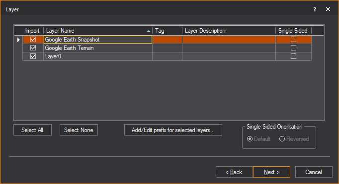
6In the Layer window, select the layers that you want to import.
nIf there is more than one layer listed, you can select multiple layers simultaneously by pressing CTRL on your keyboard and then clicking on the desired layers.
nFor each layer that you want to import, ensure that the Import checkbox is checked. If you do not want to import a certain layer, highlight it and clear this checkbox. For example, if you have drawn both a venue and elements in SketchUp and you have put them on separate layers, you can choose to only import a particular element into the WYSIWYG file by selecting the appropriate layer in this window.
7To add a description to the layer, enter the information in the Layer Description field of the layer.
8To add metadata to the layer, enter in a descriptive tag in the Tag field of the layer.
9To import a single-sided layer, highlight the layer and select the Single Sided checkbox.
Note: Single-sided layers use less processor time to display in Shaded views and to render in the Render Wizard. However, they only appear properly in each of these views if the faces of the object are drawn facing outward. Unless you know how the SketchUp file was drawn, it is recommended that you leave Single Sided deselected by default when importing the layers so that the object appears correctly. Note that you will not be able to see “through” the walls of an imported double-sided venue when you rotate the image around in the Shaded view (unlike the WYSIWYG venues, which are single sided).
If the imported object does not appear correctly in the Shaded view, you can change its sidedness by using the Properties window. You can change it from single sided to double-sided, or vice versa. You can also flip the object’s sides if the wrong side is currently facing outward. For details, see “To change an object’s sidedness”.
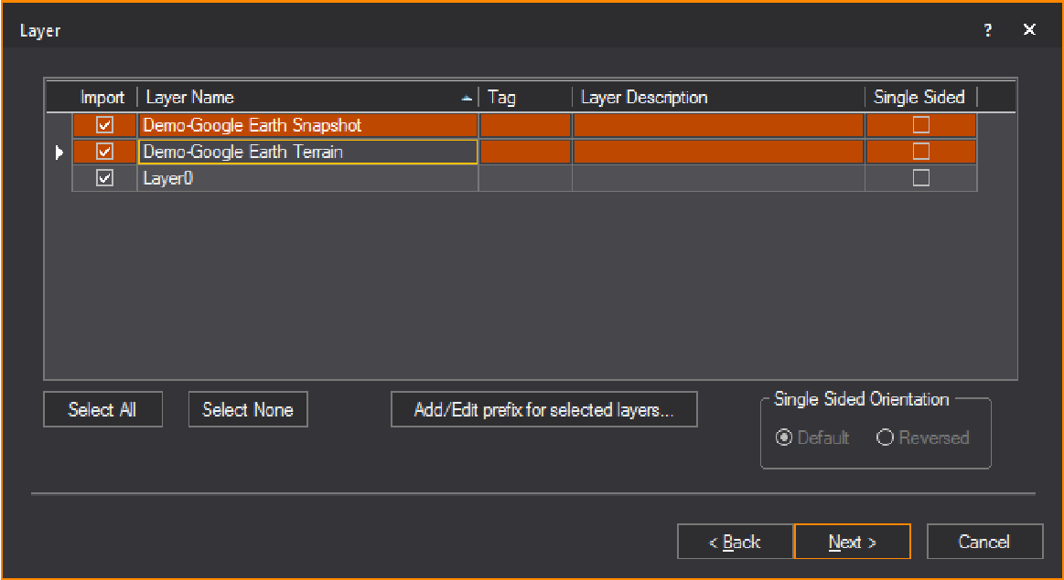
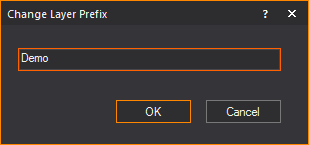
10To add a prefix to selected layers, click Change prefix for selected layers... button.
Result: The Change Layer Prefix dialog box appears.

a.In the Change Layer Prefix dialog box, enter in the desired prefix you want to add to the selected layers.
b.Click OK.
Result: The selected layers will have the prefix added to the layer’s name.
Note: If a prefix is added to a layer that previously had a prefix assigned, the new prefix will override the old prefix.
11Click Next.
Result: The Component window appears.
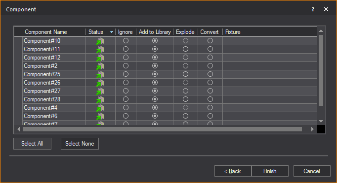
12Blocks in SketchUp are called components. If you have components in your drawing, you have the option to ignore them, explode them, convert them into a library item, or substitute WYSIWYG fixtures for the existing components.
nComponent Name: The name of the block.
nStatus: This icon  indicates
that the block is currently on a layer being imported. This icon
indicates
that the block is currently on a layer being imported. This icon  indicates that the block
is on a layer that will not be
imported.
indicates that the block
is on a layer that will not be
imported.
nBlock Type: This icon  indicates
that the block is a singular block and does not contain any sub-blocks.
This icon
indicates
that the block is a singular block and does not contain any sub-blocks.
This icon  indicates that
the block is a nested block and contains one or many sub-blocks.
indicates that
the block is a nested block and contains one or many sub-blocks.
nIgnore: Select this action to ignore the block. The block will not be added to the resulting file.
nAdd to Library: Converting a block into a library item imports the object and creates a duplicate of it to add to the library for future use. To make it available globally, see “To create a custom library item”. When you convert SketchUp files into custom library items, they appear on the Library tab of the Library Browser within the SketchUp folder.
nExplode: Exploding the component breaks it into its sub-components. That is, it breaks the block into its components. You must be careful of components that are made up of other components as WYSIWYG will only explode down one level.
Note: Exploding is not recommended. Exploding should be your last resort to import files, as it is taxing on performance.
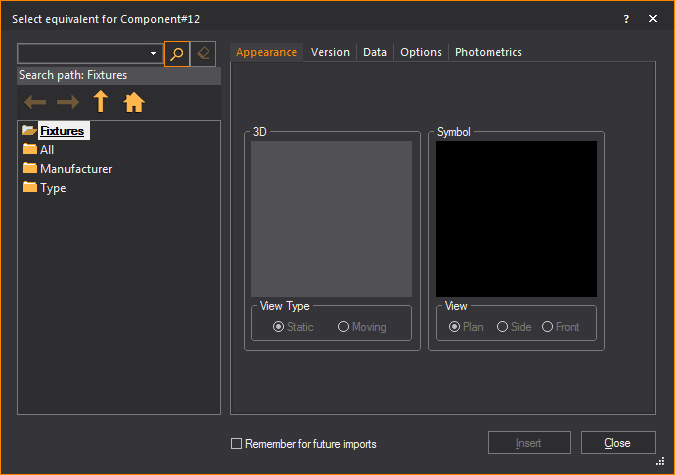
nConvert: Converting a component into a fixture replaces the SketchUp component with a WYSIWYG fixture of your choice. Once you have selected this option, select the ellipsis in the neighboring column.
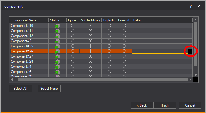
Result: The Fixture Select window appears.

13Select the fixture that you want to use to replace the block. If you find that you are always replacing a particular type of component with a specific fixture, you can set an option in WYSIWYG so that the substitution will automatically occur each time you import the component. For example, if you have files in which the ‘PAR64M’ block is always a PAR 64 fixture with an MFL bulb, you have the option of telling WYSIWYG to automatically import the component in that way. To change this option, edit the Import.lst file that is created in the Library folder (usually C:\Program Data\CAST Software\WYSIWYG\1.xx.xx.x\Library) once the first fixture is set to be remembered for future imports.
Note: WYSIWYG creates a pipe for every imported fixture since fixtures in WYSIWYG need to hang on a hang structure. If, however, fixtures are on a straight pipe represented by a straight line in the DWG file, WYSIWYG will convert the entire line into a pipe.
Tip: If you select the Remember for future imports checkbox in the Library Browser, WYSIWYG will automatically map the same fixture that appears again in the next SKP file being imported. (You can change the automatic mapping if required.)
14Click Finish.
Result: The Import Summary window appears.
15Click OK.
This procedure merges the SketchUp file into the current WYSIWYG document, placing the object in the location you specify.
At a certain point, the merging procedure is the same as the opening procedure until the end when you choose where to place the object you are merging.
Before you begin
You must have the SketchUp file saved on your computer to begin this procedure.
1Open the WYSIWYG file into which you want to add the SketchUp file.
2From the File menu, choose Merge.
Result: The Merge dialog box appears.
3In the Merge dialog box, beside the File name box, select SketchUP Files (*.skp) from the drop-down list.
4Locate the location of the SketchUp file on your computer. Select the file and click Open.
Result: The Merge dialog box changes asking for a Base point.

5Select the radio next to the desired Base point.
6Click OK.
7Follow procedure Steps 3 to 14 from the “To open sketchup files” section. At this point, the steps are the same until the end when you choose where to place the object you are merging.
Result: The Merge Summary window appears.
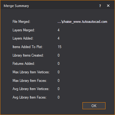
8Click OK.
9If you chose Select Basepoint with mouse in Step 5, click to place the object in the drawing.
When importing a .DWG/.DXF file into WYSIWYG, you have two options:
nYou can open a .DWG/.DXF file.
nYou can merge a .DWG/.DXF file into an existing WYSIWYG document.
If you open a .DWG or .DXF while another show document is currently open, you are prompted to save changes to that document before another show document is opened. Only one show document may be open at a time. When you merge documents, it enables you to add the contents of the .DWG or .DXF file to the contents of the current document.
3D solids contained within an AutoCAD file are automatically placed inside blocks by AutoCAD. When you import any file that contains a block, WYSIWYG will automatically explode the blocks in the DXF or DWG files for you if you decide to do this before opening them in WYSIWYG.
Note: WYSIWYG supports .dwg or .dxf files from AutoCAD version 2018 format and earlier at the time of this release.
The DWG/DXF entities that can be imported are detailed in the following table. The resulting WYSIWYG objects are also shown.
DWG/DXF entity |
WYSIWYG object |
|---|---|
Circle |
Circle |
Point |
Point |
Arc |
Arc |
Line |
Line |
Leader |
Line and Text |
MLeader |
Line and Text |
Ellipse |
Circle or line* |
2D Polyline |
Line |
3D Polyline |
Line |
Mline |
Line |
Spline (see Note) |
Spline or Line |
Text |
Text |
MText |
Group of text items |
Polyface Mesh (PFACE) |
Set piece |
Polygon Mesh (3D Surfaces) |
Set piece |
Face (3D Face) |
Surface |
Aligned dimension |
Dimension |
Rotated dimension |
Dimension |
Region |
Surface |
Cylinder |
Cylinder |
Sphere |
Sphere |
Cone |
Cone |
Box |
Riser |
Planar Surface |
Surface |
Revolved Surface |
Set Piece |
Helix |
Line |
Lines with bulges |
Lines and Arcs |
Attribute Text |
Text Label (with attributes substituted) |
* A closed AutoCAD ellipse will be imported as a circle; otherwise, it is imported as a multi-segment line.
Entities that can be imported as a library item
nCircle
nArc
nLine
n2D Polyline
n3D Polyline
nPolyline
nMline
nPolyface Mesh (PFACE)
nPolygon Mesh (3D Surfaces)
nFace (3D Face)
nSpline
nEllipse
nRevolved Surface
nHelix
nText and MText (See Note)
Note: Text and MText entities in blocks are not integrated directly into library items (a feature WYSIWYG does not support). However, a copy of each Text or MText entity is extracted from the block and inserted into WYSIWYG document as a text label. Attributes are substituted.
Limitations
nMultilines becomes single lines.
nMultiline text becomes a group of individual text items, with each line represented by its own item.
Note: The formatting for each line is taken from that of the first character of the line, except in the case of bullets, in which case the first character after the bullet point is used.
nSegments that are not straight (for example, arcs) become straight line segments.
nA spline must contain “Fit” data for it to be imported. When a Spline is initially drawn in AutoCAD, it is defined by a series of user-provided Fit Points, which are automatically converted to Control Points by AutoCAD. To import Splines into WYSIWYG properly, you must maintain the Fit Points that define the Spline. If the Spline is defined only by Control Points, it will import into WYSIWYG as a regular line, with additional points to help follow the curvature.
nStretched (scaled) blocks are not supported.
nBlocks to be converted to library items cannot imbed other blocks.
nBlocks to be replaced by a fixture cannot imbed other blocks.
Tip:
nDo not import 2D/3D solids whenever possible. Instead, use 3D Face and 3D Surface entities.
nIt is recommended that you explode Polyface Mesh or Polygon Mesh entities in AutoCAD before importing to WYSIWYG so you can access each face in WYSIWYG.
Before you begin
Clean up the CAD file by removing all unnecessary layers, such as doors, windows, and architectural details. Generally you want to remove items that you do not need to see or will not use in the plot.
Use the Purge command in AutoCAD to remove layers, blocks, and so on, that are not wanted or needed. You may want to do this several times since layers and blocks are sometimes linked to other parts of the drawing, and the Purge command might not pick them up the first time. The more unwanted items you can remove, the smaller the file size will be, and the easier/faster it is to import.
This procedure creates a new WYSIWYG document from the imported DWG/DXF file. If you are already working in a document, you are prompted to save any changes and close the document before you import the file into WYSIWYG.
1From the File menu, choose Open.
2From the files of type box, select the DWG or DXF type. Files of this type appear in the browser window.
3In the browser, click the file name, and then click Open.
Result: The Pre-Processing Options window appears.
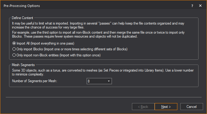
4In the Pre-Processing Options window, you can specify which DWG/DXF blocks and non-block entities are converted into Library items.
a.From the Define Content section, choose which layers and items will be converted into your drawing.
nSelect the Import All radio button to include in the import, all blocks, block references, all non-block items and layers for conversion into your drawing. You can import all entities in one pass if you select this option.
nSelect the Only import Blocks radio button to include in the import, only items that are blocks and block references for conversion into your drawing. You can import one or more times selecting different sets of blocks if you select this option.
nSelect the Only import non-block entities to exclude from the import, all items that are blocks and block references. You can import only once if you select this option.
b.From the Number of Segments per Mesh drop-down list in the Mesh Segments section, choose the number of segments that will affect how the Library Items and Set Pieces are converted into your drawing. Blocks with higher number of segments consume more memory which affect the performance of your computer hardware.
c.Click Next.
Result: The Working dialog box appears showing the Pre-processing progress bar, and then the Scale window appears.

5Select the unit type used in the DWG/DXF drawing.
6Click Next.
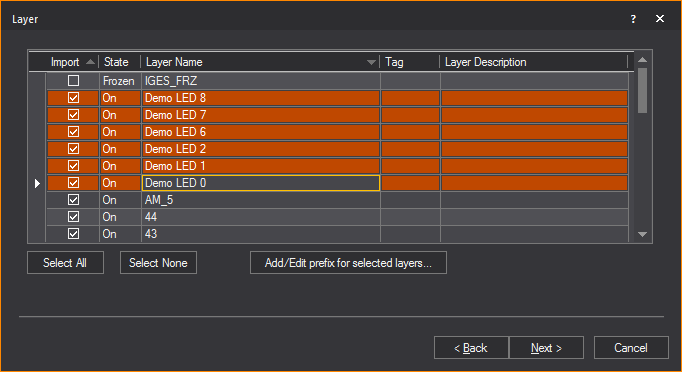
Result: The Layer window appears.

7Highlight the layers that you want to import. Note that you do not need to import all the layers at once. Refer to “Importing scenario” for suggestions on how to import the various layers. For each layer that you want to import, ensure that the Import checkbox is checked. If you do not want to import a certain layer, highlight it and clear this checkbox.
Note: In the Layer window, the State column shows the state of the layer in the DWG/DXF file. Frozen layers are not selected for import by default. Off layers are selected but will be set to Not Visible in WYSIWYG after import.
8To add a description to the layer, enter the information in the Layer Description field of the layer.
9To add metadata to the layer, enter in a descriptive tag in the Tag field of the layer.
10To add a prefix to selected layers, click Add/Edit prefix for selected layers... button.
Result: The Change Layer Prefix dialog box appears.
a.In the Change Layer Prefix dialog box, enter in the desired prefix you want to add to the selected layers.
b.Click OK.
Result: The selected layers have the prefix added to the layer’s name.
Note: If a prefix is added to a layer that previously had a prefix assigned, the new prefix will override the old prefix.
11Click Next.
Result: The Block window appears.

12If you have blocks in your drawing, you have the option to ignore the blocks, explode the blocks, convert them into a library item, or substitute WYSIWYG fixtures for the existing blocks.
Note: 3D solids are automatically placed inside blocks by AutoCAD, and assigned an abstract block name (for example, *X1). The number of “blocks” that are found are dependent on the number of solids that were in the AutoCAD file. You will be prompted to determine what action to take for each type of “block.”
nBlock Name: The name of the block.
nStatus: This icon  indicates
that the block is currently on a layer being imported. This icon
indicates
that the block is currently on a layer being imported. This icon  indicates that the block
is on a layer that will not be
imported.
indicates that the block
is on a layer that will not be
imported.
nType: This icon  indicates
that the block is a singular block and does not contain any sub-blocks.
This icon
indicates
that the block is a singular block and does not contain any sub-blocks.
This icon  indicates
that the block is a nested block and contains one or many sub-blocks.
indicates
that the block is a nested block and contains one or many sub-blocks.
nIgnore: Select this action to ignore the block. The block will not be added to the resulting file.
nAdd to Library: Converting a block into a library item imports the object and creates a duplicate of it to add to the library for future use. Note that the component will lose all surface properties, such as color and texture, and it will only be available in the library of the current document. To make it available globally, see “To create a custom library item”. When you convert DWG or DXF files into custom library items, they appear on the Library tab of the Library Browser within the DWG or DXF folder.
nExplode: Exploding the component breaks it into its sub-components. That is, it breaks the block into its components. You must be careful of components that are made up of other components as WYSIWYG will only explode down one level.
Note: Exploding is not recommended. Exploding should be your last resort to import the file, as it is taxing on performance.
nConvert: Converting a component into a fixture replaces the DWG/DXF component with a WYSIWYG fixture of your choice. Once you have selected this option, select the ellipsis in the neighboring column.
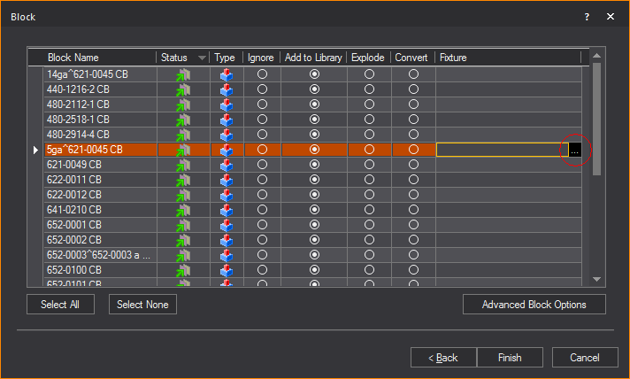
Result: The Library Browser window appears.
13Select the fixture that you want to use to replace the block. If you find that you are always replacing a particular type of component with a specific fixture, you can set an option in WYSIWYG so that the substitution will automatically occur each time you import the component. For example, if you have files in which the ‘PAR64M’ block is always a PAR 64 fixture with an MFL bulb, you have the option of telling WYSIWYG to automatically import the component in that way. To change this option, edit the Import.lst file that is created in the Library folder (usually C:\Program Data\CAST Software\WYSIWYG\1.xx.xx.x\Library) once the first fixture is set to be remembered for future imports.
Note: WYSIWYG creates a pipe for every imported fixture since fixtures in WYSIWYG need to hang on a hang structure. If, however, fixtures are on a straight pipe represented by a straight line in the DWG file, WYSIWYG will convert the entire line into a pipe.
Tip: If you select the Remember for future imports checkbox in the Library Browser, WYSIWYG will automatically map the same fixture that appears again in the next DWG/DXF file being imported. (You can change the automatic mapping if required.)
14Click Advanced Block Options to filter objects within the block based on their layer.
Result: The Advanced Block Options dialog box appears.
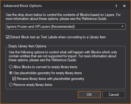
Use the drop-down menu to control how the contents of incoming Blocks should be handled based on the layers on which the Blocks’ components reside.
nIgnore Frozen and Off Layers (Recommended): This is the preferred option in most cases, since it offers the best optimization for the import: no parts of Blocks that are on layers which have been turned Off and/or Frozen will be imported. Once the import is complete, what you see will most-closely match what is seen when this file is opened in AutoCAD or DWG TrueView—with the exception of DWG entities that cannot be imported at this time. (Use the radio buttons in the Empty Library Item Options section to control how to deal with such entities.)
nIgnore Only Frozen Layers: Choosing not to import parts of Blocks that are on layers which have been Frozen will skip those parts, but parts that are on layers which have been turned Off will import. This will lead to a potentially more complete, but also more complex model—but entities that cannot be imported at this time will still not import. It is important to remember that if you chose to convert such Blocks to DWG Library Items, you will have no control over them: you will not be able to “edit” the DWG Library Item in order to “remove” from it the parts which were imported from the layers that were Turned Off.
nIgnore All Layers Not Being Imported: This option offers layer-based control over which parts of a Block should be ignored for import: entities which exist on layers that you have chosen not to import (in the previous step of the DWG/DXF Import Wizard) will not import. It is recommended that you only select this option if you are very familiar with the contents of the file you are importing AND when you are performing a “multi-pass” import (i.e. importing the same file multiple times, with different options and/or with only handful layers at a time).
nImport Everything (All Layers): This option should only be used when the previous options fail to yield the desired import result, and should (ideally) only be chosen when a single Block, or only a handful of Blocks, are selected for import; while it will lead to a complete import (with the exception of DWG entities that cannot be imported at this time), the resulting model (DWG Library Item) may look altogether different than what you see when you open the file in AutoCAD or DWG TrueView. In addition, the model may end up being very complex, which can lead to performance issues. Use this option with caution, and, ideally, only when performing a “multi-pass” import.
nExtract Block text as Text Labels when converting to a Library Item: Since WYSIWYG’s Library Items cannot contain text, Text or MText objects contained within Blocks being imported would have to be discarded; select this option (recommended) in order to extract text from such Blocks and add it to the resulting .wyg file as a Text Label object.
nEmpty Library Item Options: Use the radio buttons in this section to control what will happen with Blocks which only contain entities that cannot be imported, if you choose to convert them to DWG Library Items; these options will not affect DWG Blocks that you have chosen to Explode.
nAllow Blocks to convert to empty Library Items: This option will allow such blocks to convert into empty/”zero-length” DWG Library Items. You will not be able to select them, and inserting them will result in a non-selectable item. Not recommended.
nUse placeholder geometry for empty library items: This option (recommended) will replace entities contained in such Blocks with a 1m “Spike” DWG Library Item.
nRename library items with placeholder geometry: Enable this checkbox to add a “PH” prefix to all such DWG Library Items.
nRemove empty library items: When this option is selected, all such Blocks will be ignored: no empty Library Items will be created, but at the same time, there will be no indication whatsoever that something was supposed to be there. Only select this option if you are sure that you do not require that information.
a.Click OK to apply the set options and close the Advanced Block Options dialog box.
15Click Finish.
Result: The Import Summary window appears.

16Click OK.
The CAD importing guide
For more detailed information about importing DWG/DXF files, please read through the CAD Importing Guide, at
https://cast-soft.com/wysiwyg/cad-importing-guide/.
This procedure inserts the imported DWG/DXF file into an existing WYSIWYG document in the location of your choice.
At a certain point, the merging procedure is the same as the opening procedure until the end where you choose where to place the object you are merging.
1From the File menu, choose Merge.
Result: The Merge dialog box appears.
2In the Merge dialog box, beside the File name box, select DWG or DXF Files (*.dwg or .dxf) from the drop-down list.
3Locate the location of the DWG file on your computer. Select the file and click Open.
Result: The Merge dialog box appears asking for a Base point.

4Select the radio next to the desired Base point.
5Click OK.
6Follow the procedure Steps 3 to 15 of the “To open a dwg/dxf document” section. At this point, the steps are the same as with opening until the end when you choose where to place the object you are merging.
Result: The Merge Summary window appears.

7Click OK.
8If you chose Select Basepoint with mouse in Step 4, click to place the object in the drawing.
The CAD importing guide
For more detailed information about importing DWG/DXF files, please read through the CAD Importing Guide, at
http://cast-soft.com/wysiwyg/cad-importing-guide/.
You do not need to import everything in your file at once. You can import items one by one or separately to ensure accuracy. The following scenario may help you when importing DWG/DXF files into WYSIWYG:
1After choosing to open a DWG/DXF file, switch to the Layers tab in the Select DWG Settings dialog box. In this tab, you can clear the layers that you do not want imported in the first round. For example, you may only want to import the venue and all the layers related to it. In the case of a 2D CAD drawing, it is easier to extrude lines into walls and do everything else needed to complete the virtual venue. It will also be quicker as WYSIWYG will have a lot less objects with which to work.
2Once you have completed working on the venue, you may want to merge in the hang structures if they exist in the CAD file. Using the Merge command from the File menu, you can open the same CAD file once again, and choose the appropriate layer(s) from the Layers tab. When WYSIWYG asks you to pick the insertion point, make sure you select Use 0,0,0 as Basepoint. This will ensure that everything in the new layer is placed accurately in the WYSIWYG plot.
3Continue in the same manner with fixtures and the other objects. Note that if in the CAD file the fixtures exist on different layers, you may want to bring these in separately/one by one as well.
If you need to send your WYSIWYG drawings to someone using another drafting program, you can export your file to the DWG or DXF file type. DWG and DXF formats are used to transfer documents to AutoCAD or other compatible drafting applications.
Entities that can be exported
n2D DWG/DXF: When you export WYSIWYG objects to a 2D DWG/DXF file, all objects, including fixture attributes, are converted to lines.
n3D DWG/DXF: The objects that can be exported to a 3D DWG/DXF file and the resulting DWG/DXF entities are shown in the following table. Fixture attributes cannot be exported to 3D DWG/DXF.
WYSIWYG object |
DWG/DXF entity |
|---|---|
Line |
3D Polyline |
Spline |
Spline |
Point |
Point |
Circle |
Circle |
Arc |
Arc |
Text |
Text |
Pipe |
Line |
Rigging Point (3D) |
Block - line, circle, text |
Dimension |
Lines and MText |
Callout |
Leader |
All other objects |
PolyFace Mesh |
Note: You cannot export truss.
Limitation
The slope near the end of two lines may be slightly off.
Note: When you export WYSIWYG objects to a 2D DWG/DXF file, all objects, including fixture attributes, are converted to lines.
1From the File menu, choose 2D DWG/DXF Export.
2In the Export dialog box, navigate to the location where you want to save the exported file. Ensure that the destination appears in the Save in drop-down list.
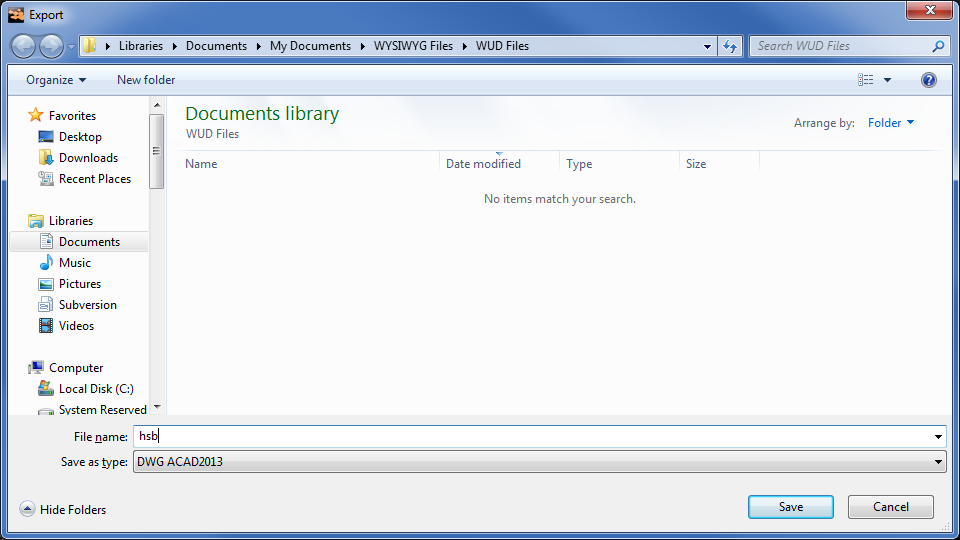
3In the File name box, type the name of the exported file.
4From the Save as type drop-down list, choose the exported file type. There are a number of choices available for file type, based on AutoCAD versions.
5Click Save.
Result: The Select DXF/DWG Settings For Export dialog box appears.

6On the Scale tab, click the option button for the units to be used in the DWG/DXF drawing.
a.To specify a custom unit of measurement, select the Custom option button.
b.In the DXF Unit To boxes, specify the mapping of the units of measurement to use in the exported file.
7Click OK.
Note: The current type of the drawing will be used as the point of view in the exported 2D drawing.
To export to dwg/dxf in 3D
Note: When you export WYSIWYG objects to a 3D DWG/DXF file, the resulting DWG/DXG entities vary. For details, see the table on “Exporting dwg/dxf files”.
1From the File menu, choose DWG/DXF Export.
Result: The Export window appears.

2In the Export window, navigate to the location where you want to save the exported file. Ensure that the destination appears in the Save in drop-down list.
3In the File name box, type the name of the exported file.
4From the Save as type drop-down list, choose the exported file type. There are a number of choices available for file type, based on AutoCAD versions.
5Click Save.
Result: The Select DXF/DWG Settings For Export dialog box appears.

Note: You cannot export a 3D drawing from WYSIWYG Report.
6On the Scale tab, click the option button for the units to be used in the DWG/DXF drawing.
a.To specify a custom unit of measurement, select the Custom option button, and then specify the mapping of the units of measurement to use in the exported file, in the DXF Unit To boxes.
7Click the Layer tab.
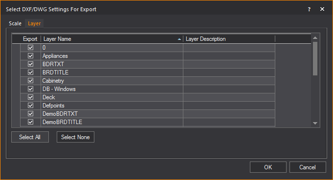
8Select the layers that you want to include in the DWG/DXF drawing by highlighting them and ensuring that the Export checkbox is checked.
a.Click Select All to select all the layers that are listed.
b.Click Select None to deselect all layers.
9Click OK.
Wavefront/filmbox/collada/3DS/gltf files
WYSIWYG allows the import of models created in GL Transmission Format (.GLTF), Wavefront (.OBJ), Filmbox (.FBX), Collada (.DAE), and 3D Studio Max (.3DS) for use in WYSIWYG. These models will be imported as one object, and their colors, texturing and materials will be preserved in the import.
Note: Any properties which are not supported by WYSIWYG will be lost from the model on import.
To import gl transmission format (.GLTF) / wavefront (.OBJ) / collada (.DAE) / filmbox (.FBX) / 3D studio (.3DS) files
Note: This procedure creates a new WYSIWYG document from the imported object file. If you are already working in a document, you are prompted to save any changes and close the document before you import the file into WYSIWYG.
1From the File menu, choose Open.
Result: The Import window appears.

2In the Import window, from the File Type drop-down list, select the desired file type you want to import. Files of this type will be visible in the window.
3Navigate to the desired file, click the file name, and then click Open.
Result: The Scale window appears.

4From the The Model was drawn in a 3D software where drop-down list, select one of the following that describes how the software in which the object was drawn defines its 3D space.
Note: If you do not have this information, inquire with the person who created the model you are importing, or view the model in a model viewer such as in order to determine its orientation. You may also leave this option at its default (Z-axis points up) and if the object is not oriented correctly once imported, Rotate it as required.
nZ - axis points up
nY - axis points up
5From the The Model’s Base Point should be located drop-down list, select one of the following that describes where the base point of the object should be:
nExact Center
nBottom Center
nAverage Center
nDon’t Change
a.To have the insertion point of the model act instead as the base point, select the Move Model Base Point to Insertion Point checkbox.
6In the Model is in following Scale section, select the radio next to the scale you want to use for the model.
a.If Auto-Scale was selected, select the checkbox under the Auto-Scale radio to change how the object will be auto-scaled. Edit the auto scale as desired by editing the following fields/drop-down lists next to the radio:
nScale Model to a length of [number] [units of measure] along Model’s [axis/side of model]
7In the Mesh Decimation section, select the Reduce Polygons in your Model to checkbox to redraw and reduce the number of polygons in the model based on the original model.
Note: Mesh Decimation is the process by which the number of polygons that make up a model/object is reduced, without altering its size and overall shape.
a.Select from the drop-down list the percentage of polygons to reduce.
8In the Mesh Decimation section, select the Reduce Polygons in your Wireframe Model to checkbox to reduce the number of lines used to display the model being imported in the wireframe views.
a.Select from the drop-down list the percentage of polygons to reduce.
Note: Choosing a low percentage will increase Wireframe view performance after geometrically complex models have been imported. However, enabling only this option (i.e., not also enabling Reduce Polygons in your Model to) will result in good Wireframe performance, but poor Shaded view performance. Therefore, if the model being imported requires decimation, it is best to enable both options and choose the same percentage value for both.
9Click Finish.
Result: The Import Summary window appears.

10Click OK.
Result: The object is imported into WYSIWYG.
You can export WYSIWYG files complete with textures in the GL Transmission Format (.GLTF). This option is available in the Shaded view tab in CAD mode or an active Shaded view pane in any other CAD view tab (including Custom Tabs).
In WYSIWYG, you can export the following textures to the glTF material: base color, color texture, normal map, single sided, or double sided.
When a “.gltf” file is exported, an accompanying “.bin” file is created and any textures that were applied to objects (whether from WYSIWYG Texture Library or Image Sources) are saved as individual “.png” files in the same location as the exported file. For convenience, all these files are automatically deposited into a folder of the same name as the exported GLTF file.
Notes:
nTransparency (including transparency from Alpha textures) and other Material properties are not supported for export.
nFixtures do not behave as light sources in the application where the resulting “.gltf” file was opened.
To export shaded view to glTF
1From the File menu, choose GLTF Export.
Result: The GLTF Export window appears.

2In the GLTF Export window, navigate to the location where you want to save the exported file.
3In the File name box, type the name of the exported file.
4From the Save as type drop-down list, choose GLTF Files (*.gltf) type.
5Click Save.
Result: The shaded view is saved in glTF file format; the .gltf file, and the accompanying .bin and .png files are created in a new folder of the same name as that entered for the GLTF file within the selected location.
If you have an existing floorplan saved in bitmap (.bmp), JPEG (.jpg), GIF (.gif), TIFF (.tif), PNG (.png), Targa (.tga) or Portable Document Format (.pdf), you can import it into your drawing using the Floorplan Importing Wizard, and then use WYSIWYG's Drawing Tools to "trace" it and, in so doing, create a 2D, then a 3D model of the venue in the floorplan.
You can import floorplan images in 3 view types:
nPlan: Floorplan images in Plan view can be imported into Wireframe that is set to Plan View Type.
nFront/Back: Floorplan images in Front or Back profile views can be imported into Wireframe that is set to the Front or Back View Type.
nLeft/Right: Floorplan images in Left or Right profile views can be imported into Wireframe that is set to the Left or Right View Type.
Notes:
nYou can print with Imported Floorplans from CAD mode Wireframe, New Plots and Layouts in PRES mode.
Attention: Imported floorplans are a purely visual feature without any guarantee of accuracy and precision in the printed document. When printing a floorplan, a Warning dialog box appears asking for you to acknowledge that there are no guarantees about the content, accuracy, precision, or anything else in the printed document and that you will not hold CAST responsible for any errors or inaccuracies in the document. Select the checkbox and click OK to proceed.

nThe images in the profile views allow you to import wall outlines for the room that you are building in your 2D drawing.
Before you begin
Before you import a floorplan, you must know the precise dimensions of at least one of the elements in your imported floorplan. For example, if it contains a stage, note the width of the stage before you import the graphic into your drawing. The floorplan should also be to scale.
To import a floorplan
1In either the Wireframe or Quad tab, in Plan view, click File > Import Floorplan.
OR
in Front or Back view, click File > Import Floorplan... > Front/Back.
OR
in Left or Right view, click File > Import Floorplan... > Left/Right.
Result: The Floorplan Importing Wizard window appears.

2In the window click Browse.
Result: The File Browser window appears.
3In the File Browser window, navigate to your floorplan file, select it, and then click Open.
Result: The file browser window closes. The location of the floorplan image will be in the Browse field.
4Click Next.
Result: The wizard will switch to the Rotate Floorplan page. Here the floorplan image can be rotated 0°, 90°, 180° or 270°.
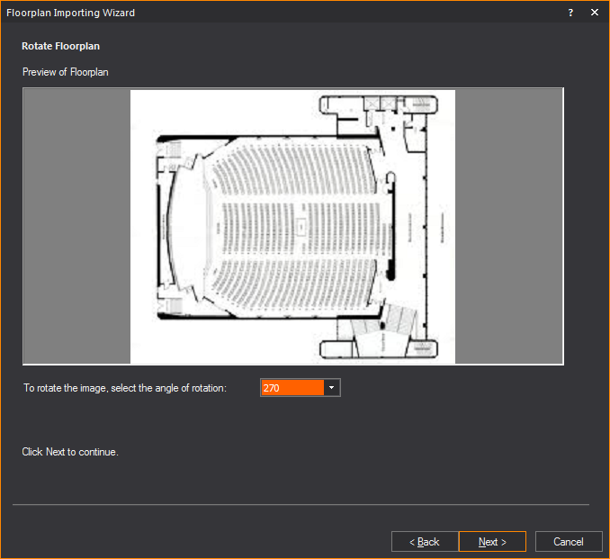
5Select the angle of rotation for the floorplan, then click Next.
Result: The wizard will switch to the Define Anchor Point page. You can select from predefined anchor points or create your own.

6Select the anchor point of the floorplan, from the Anchor drop-down list.
a.If a custom anchor point was selected, click a point in the floor plan to create the anchor point.
7Click Next.
Result: The wizard will switch to the Define Insertion Base Point page. The anchor can be inserted at either the origin or a user selected point.

8Define the insertion base point, then click Next.
a.If a user selected point was chosen, the wizard window will minimize. Click on a point in the WYSIWYG file where you want the insertion point to be.
Result: The wizard will switch to the Specify Floorplan Scale page. Here a dimension line is drawn between two points of the floorplan to determine its scale.

9Ortho X and/or Ortho Y can be enabled to ensure any dimension line drawn is parallel with the respective axis.
Note: This step can be skipped if you are modifying a previously imported floor plan, by selecting the box next to Skip this Step....
10Click Next.
Result: The window will minimize and show the floorplan inserted into WYSIWYG.
11In the floorplan image, choose an item in your drawing whose measurements you know, and then click on one end of the item. For example, if you know the dimensions of the stage, click on one corner of it.
12Click on a second end of the item. For example, if you had clicked on one edge of the stage, click on an opposite edge of it.

Result: The Import Floorplan window will reappear, prompting you to enter the length of the line that you have just drawn.

13Type the length of the line, and then click Next.
Result: WYSIWYG adjusts the size of the floorplan based on the scale that you have entered to ensure that your drawing is accurate. The floorplan appears in your drawing in plan view (the only view in which you can see it).
14Click Finish to finish editing the floorplan. Click Back to change any of the previous settings.
Tips:
nOnce you import the floorplan, you can hide it from sight by right-clicking on your drawing and selecting Hide Floorplan. To show the floorplan again, simply right-click and select Show Floorplan.
nTo modify the properties of the floorplan after it has been inserted, right-click the floorplan image and select Modify Floorplan.
Note: You can delete floorplans, but once deleted, the floorplan must be re-imported in order for it to be available once again. Since this process may affect the measurements set in the above procedures, it is recommended that you only delete floorplans once your show is “finalized".
Fixture information listed in a spreadsheet file (CSV, XLS, XLSX) that was exported from other software and/or lighting consoles can be imported into your drawing using the Fixture Import wizard. The fixture objects listed in the spreadsheet will be inserted into your drawing according to the settings that were included in the spreadsheet.
Fixture Import option enables you:
nTo define the file for import and the unit type.
nTo map your file’s column headers to match the appropriate WYSIWYG fixture property (e.g. Fixture type, position X Y Z, rotation Rx Ry Rz, Fixture ID, patch, channel, etc.)
nTo match fixtures that are not recognized with the corresponding fixtures from the WYSIWYG Library.
To import fixtures
1In either the Wireframe or Quad tab (not in Shaded view), click File > Import Fixtures...
Result: The Fixture Import window appears.

2In the Fixture Import section, click the ellipsis button to browse and select the spreadsheet file with the fixture data you wish to import.
3The file location that was selected will be displayed in the Fixture Import box.
4Select the Treat first row as column headers checkbox if you want the first row of your spreadsheet to be displayed as the column headers.
5In the Spreadsheet is in section, click the radio button to choose which unit of measurement were used in your spreadsheet.
6Click Next to continue.
Result: The Fixture Import Preview window appears with the fixture data in the table.

7In the row at the top indicated with the blue arrow, click the drop-down arrows in each column to map your spreadsheet headers to the appropriate WYSIWYG column headers. For example, starting with the Type drop-down list, click to make sure that the matching header is selected. Proceed through each of the columns to map all the headers of columns that you wish to import.
Notes:
nFor any column that you do not wish to import, set the drop-down list to Ignore.
nOnly fixtures with checked boxes will be imported. Columns are highlighted in pink color if the data listed are not recognized and do not match with information in WYSIWYG.
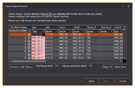
a.To correct the invalid data, click on the highlighted cell(s) and type to change the value, or click on the ellipsis button to browse the selected fixture attribute.
Result: The Library Browser window appears.
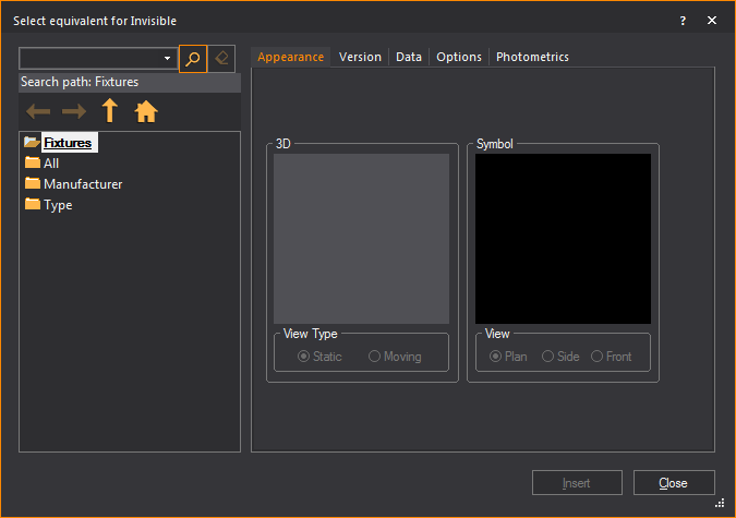
b.In the Library Browser window, browse and choose the object and settings to match the selected fixture that will be imported.
c.In the Library Browser window, click Insert.
Result: The WYSIWYG confirmation dialog box appears where you may choose to replace all instances of the selected fixture type.
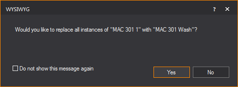
d.Click Yes.
Result: The fixture data in the spreadsheet is replaced with settings that match the WYSIWYG Library. All selected rows (checkbox in the left-most column) must have valid information to proceed with the import process.
8You can ignore any fixtures or objects in the spreadsheet and proceed with the import. Click Uncheck Invalid Fixtures to select only the valid fixtures without error settings.
9Click Select All to choose and import all the fixtures listed in the table.
10Click Select None to clear all the fixtures and import none.
Note: In the Fixture Import Preview window, error messages indicating conflicts are displayed in red text, and the table columns with the unrecognized fixture data are highlighted in pink color. The values in the rows can be changed to resolve conflicts.
11Click Finish.
Result: The fixtures are inserted in your drawing in the specified layout and with all the settings in the spreadsheet. Every fixture will appear hanging on its individual hang structure.
Tip: You can use Relocate Fixtures to relocate imported fixtures from collinear pipes to other hang structures. For information on Relocate Fixtures, see “Relocating and cloning fixtures”.
An essential component of WYSIWYG is its extensive library. You can browse the contents of the library in the Library Browser, choosing from a multitude of 3D objects to add to your plots.
Working with the Library Browser
The Library Browser is dockable, which means that it has a grab bar on the top that is used to move it around the screen. You can place it on the edges of the work area, at the top, bottom, left, or right. You can also drag it off the edge of the work area and into its own window. This window remains on top of the WYSIWYG screen and may be dragged anywhere.
Note: If you experience difficulty undocking the browser, hold down the CTRL key while dragging the grab bar.
1From the Library menu, choose Browse Library.
Tip: You can also click the Library on the Draw toolbar.
Note: You can also access the Library Browser from the Options menu on the Welcome window when a document is not opened.
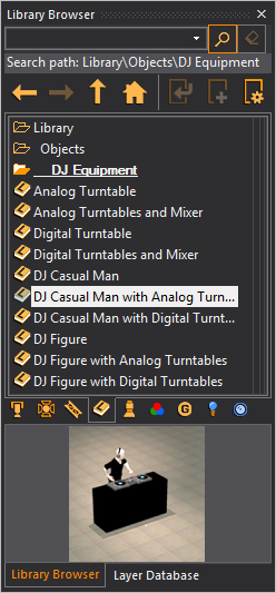
2Click any of the tabs along the bottom of the browser window to view the contents of different sections of the library. The library is divided into the following sections:
n Fixtures
n Accessories
n Truss
Truss
n Library
Items (scenic)
Library
Items (scenic)
n Symbols
n Gobos
Gobos
n Lenses
Library entries are divided into sort criteria. These criteria may be organized alphabetically, by manufacturer, by type, or by other pertinent classifications. For example, you can find the ETC Source 4 in the Fixtures section > Manufacturer > EFGH > ETC > ERS sub-menu.
Depending on the library item that you click, you may see a sample image of the item in the preview pane at the bottom of the browser.
You can save time by using the Library Search feature. In the Library Browser, simply click the category tab that you are interested in, and then type the object name (or part of it) in the Search box at the top of the browser panel. All objects that match your query are shown.
1Open the Library Browser.
2Click the category tab that you are interested in. For example, click Fixtures.
3In the Search box, type the name of the item that you are searching for, or a partial name. For example, if you are searching for the CE Source 4 Par, you could type “par”.
4Click the Search icon.
|
The Search button. |
Result: The results of your search appear in the browser pane.
Tips:
nTo return to the top level of the current category, click the Home icon.
|
The Home button. |
nTo clear the search, but remain in the current category, click the Clear button.
|
The Clear button. |
To view the properties of library objects
1Open the Library Browser.
2Navigate to and select the desired object.
3Click the Property tool at the top of the Library Browser.
|
The Properties button. |
4Repeat steps 2-3 to view the properties of multiple objects. You may want to open the properties of different objects to compare data, such as photometric information.
Tips:
nYou can also hold the ALT key and double-click on the object name.
nTo view library objects without opening property windows, browse the library using the shortcut bar. To do this, select the shortcut bar for the type of object you want to view. Right-click in the shortcut bar, and then choose New <library item>. The Library Selection dialog box opens with a viewing pane included.
To insert objects from the library
1Open the Library Browser.
2Navigate to the desired object or use the Search feature to locate it (for details, see “To search the Library Browser”).
3Click the Insert tool
at the top of the Library Browser. 
Tips:
nYou can also double-click on the object name.
nFor library objects, you can activate the Library Snap tool to display the snap points and the "Default" insertion point of the Library item displayed in red if the object is not selected or green if the object is selected. When the Library object insertion begins, right-click to access and select a different insertion point from the menu list. See “Library snap”.
nFor truss objects, you can activate the Truss Snap tool to display snap points of the truss. See “Truss snap”.
Note: Fixtures may only be placed on hang structures. For more information, see “Inserting fixtures”.
4Click in your drawing to insert the object.
5Click away from the object to deselect it.
To replace inserted library objects
You can use the Replace Library Item command to quickly and easily replace one or more library items with another.
1Select the library item(s) that you want to replace.
2Right-click and choose Replace Library Item.
3In the Library Selection window, select the new type of library item.
4Click Insert.
Result: All the library items that you selected in step 1 are replaced with the item chosen in step 3.
To create a shortcut for an object
In the Wireframe and Quad views you can create shortcuts for frequently used objects, fixtures and truss. Shortcuts are tools found on the various shortcut bars to the left of the working area. Clicking a shortcut for an object is the same as finding the object in the Library Browser and using the Insert command.
1Open the Library Browser.
2Navigate to the desired object.
3Click the Create
Shortcut tool at the top of the Library
Browser. 
Result: A shortcut to the object will appear on the appropriate shortcut bar.
Tip: You can also right-click on the object name, and then select Create Shortcut.
To create a shortcut for an object already inserted
Rather than going to the Library Browser to create a shortcut, you can also create shortcuts by conveniently selecting already inserted items and using the right-click menu to create multiple shortcuts.
Note: While you can create shortcuts for multiple items at once, the items have to be of the same type (i.e. all fixtures, all truss or all objects). If you have multiple items of different types you want to make shortcuts for, it will take a separate action for each item type.
1In CAD mode, in Wireframe view, select the item(s) you want to make a shortcut for.
2Right-click and select Create shortcut for selected [Item types].
Result: A shortcut to the item(s) appears on the appropriate shortcut bar.
To modify a shortcut for a library object
1Right-click on the shortcut, and then select Properties.
Result: The Shortcut Property dialog box appears. An example of the accessories Shortcut Property dialog box is shown below.
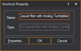
2In the Name box, type a new name for the shortcut.
The name of the fixture, color, gobo, accessories, library, or truss as listed in the library, is displayed in the Type box.
3For fixtures, you can modify the type of lens and lamp associated with the fixture by selecting the appropriate option from the Lens and Lamp drop-down lists, respectively.
4Click Properties to view the properties of the library entry.
5When you are satisfied with your selections, click OK.
To apply a texture to a library object
You can alter the appearance of library objects by applying textures to them. You can choose from thousands of textures in the WYSIWYG library or you can apply a custom texture that you have saved as a graphic file on your computer (for example, .bmp or .jpg).
Note: Since most library objects are small with complex surfaces, it is best to apply even, plain textures to them. Complicated textures containing text or other recognizable images will not display properly on small, irregular surfaces.
1Once you have inserted the library object in your plot, click on it to select it, and then right-click and select Properties.
2Click the Appearance tab.
3In the left pane, highlight the elements of the library item to which you want to apply the texture, and then click the type of texture file that you want to use, either from the Library or a custom texture that you have saved. For detailed descriptions of the texture and material options available on the Appearance tab, see “Appearance tab”.
4Click OK when you are finished.
You can create custom library items, custom conventional fixtures, custom gobos, and custom color and gobo wheels or scrolls.
When creating custom gobos and custom library items, you are given the option to make the item or gobo available to other documents, in which case the item or gobo is saved to the application’s library. If you do not choose to make the items available to other documents, the items are only saved within the one document. In either case, the items are saved and visible in the document regardless of which computer (or application) the document is opened in.
Custom conventional fixtures must be created from the WYSIWYG welcome screen and are saved directly to your application’s library. The new conventional fixture is available for you to use in all documents created using this application. If used in a show document, the custom conventional fixture is available in the document regardless of which computer (or application) the document is opened in.
Custom color, gobo wheels, and scrolls are only saved in the document and cannot be saved to the application’s library. They travel with the document, but if you need to use the same wheel or scroll on another show, you must regenerate it every time.
Note: You can delete custom library items, custom conventional fixture, and custom gobos. For information on custom library items, see “To delete a custom library item”, “To delete custom fixtures”, and “To delete custom gobos”.
To create a custom library item
See “To create a custom library item”.
To create a custom fixture
See “To create a custom fixture”.
To create custom color or gobo lists
See “To create a custom color/gobo list”.
To create a custom gobo
See “To create a custom gobo”.
Loading custom library objects on-demand
The custom library objects will be loaded on-demand when a second instance of WYSIWYG is launched. Only one instance of WYSIWYG has full permissions to edit the custom library object database, to preserve memory usage on loading of the application.
When the second instance of WYSIWYG is launched, a warning dialog box appears to inform that the second instance will be running in read-only mode.

Library Snaps are snap points drawn at the bounding box corners of the library item, and one corner is displayed in red or green to represent the library item's insertion point.
When Library Snap is enabled, all library items that are in the drawing will display their snap points, which can be used as a snap capable insertion point that will align the placement of the item in CAD Wireframe views.
When Library Snap is enabled, the insertion point is identified by a red square if the object is not selected. The red square turns to green if the object is selected. The default insertion point can be changed by selecting a different insertion point from the menu list that appears when you right-click the library item you are inserting. The cursor switches to the specified insertion point.
Notes:
nLibrary Snap only applies to objects from the Library tab in the Library Browser.
nOnce a Library Item's insertion point has been changed during insertion within the project, it is remembered for future insertions from the Library Browser, and will be used when performing some CAD operations such as Copy/Paste, Move and Rotate.
To use library snap
1From the Tools menu, choose Snap > Library.
Tip: You can also click the Library Snap tool on the CAD Options toolbar.
|
The Library Snap button. |
2Insert the library object.
Result: The library object is displayed with the snap points at its bounding box corners and the cursor is attached to the default insertion snap point displayed in green.
Note: Library Snap is automatically enabled at the start of Mirror and Paste, Move and Rotate operations in CAD mode.
To specify the library object’s insertion point
1From the Library Browser, double-click on the object name you want to insert in your drawing.
2Right-click the object to display the menu list of insertion points.
3Click on the new insertion point.
Result: The cursor switches to the specified insertion point.
Tip: The snap point options are also useful when you copy, paste and move the library objects using keyboard shortcuts.
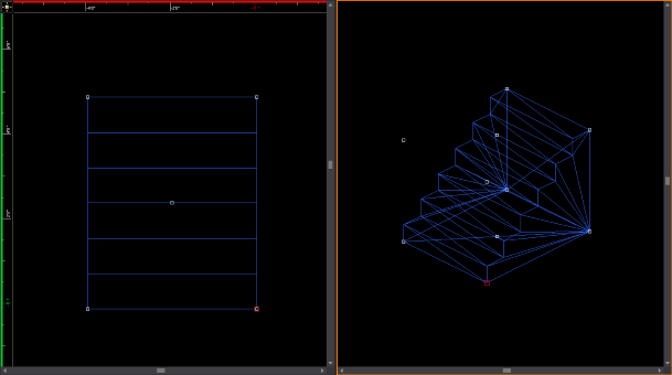
In WYSIWYG, the Draw menu lists the objects that you can draw. Keep the following tips and aids in mind when you are drawing the various objects.
nCommand Line: At any time, instead of clicking points with the mouse, you can type in the desired coordinates. When you start typing, the Command Line automatically appears in the lower left-hand corner of the window.
nShortcuts: Create shortcuts for library objects.
nMissing Coordinate: Use the missing coordinate.
nMulti-segmented lines: When you draw multi-segmented lines, surfaces, or when drawing a room using the Room Builder, the next point of the line or surface you wish to add snaps automatically to the previously drawn line/surface's endpoint, midpoint or intersection when the Endpoint Snap, Midpoint Snap and/or Intersection Snap are enabled.
nInsertion Points: Before you place a 2D/3D primitive object, screen, or LED wall, you can right-click on the object and select its Insertion Point from the menu that appears. See “Insertion points” for details.
Several commands and icons are available to help you when drawing in CAD mode. For a complete list of these aids, refer to “Keyboard shortcuts and hotkeys”.
The Room Builder tool allows you to build a custom room of any shape in Wireframe view.
To draw a custom room
1From the Draw menu, choose Room Builder.
Result: A cross-hair appears on your cursor in the drawing wireframe.
2Click to place a corner of the wall at the location of the cursor. Each subsequent click will connect the current corner to the previous corner.
3To finish the room drawing, connected the first and last created corner.
Notes:
nAlternately, the room can be closed, connected the first and last created corner automatically, by right-clicking and selecting Close Room Outline.
nTo finish a room without closing it, right-click and select Finish Room Outline.
Result: The Room Builder window appears.

4In the Room Builder window, enter in the missing characteristics of the room walls.
5Select the Place Wall objects on the opposite side of the Room Outline checkbox if you want to place object on the opposite side of the Room Outline.
6Select the Group Walls after creation checkbox if you want all created walls to be in the same group.
7Select the Close Room outline checkbox if you want to add floors or ceilings to the room.
Note: This option is only available if the room is closed. When a room is closed, WYSIWYG automatically makes the Walls transparent from outside of the room looking inwards, and makes the ceiling and floor single sided, so when the camera is outside of the room the user can see inside. These properties can be changed if the user wishes, by going to the objects' properties
8Select the Add Floor checkbox to add a floor to the room
9Select the Add Ceiling checkbox to add a ceiling to the room.
10Click Ok.
Result: The custom room is created in Wireframe view.

To begin your drawing, insert a venue.
To insert a venue
1From the Draw menu, choose Venue.
Result: A sub-menu appears prompting you to choose the type of venue to be inserted.
2Select Black Box, Arena, Proscenium Arch, Frame Tent, or Circus Tent.
Result: A dialog box appears in which you can modify the properties of the room. The Proscenium Arch dialog box is shown below.
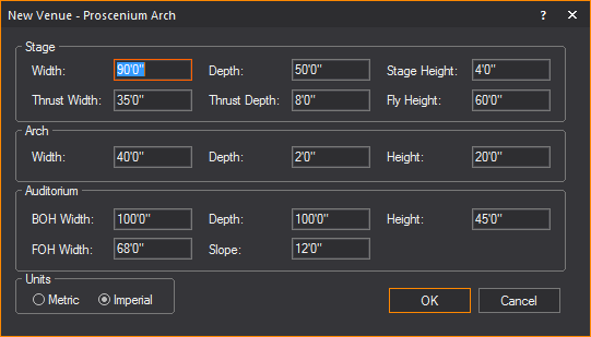
3Accept the defaults, or choose custom properties.
4Click OK.
Result: The selected venue is inserted into the drawing.
The venue types are defined as follows:
A Proscenium Arch venue is a basic theatrical space with a stage, proscenium arch, and an auditorium. The origin is set at the intersection of the center line and the proscenium line on the stage floor.
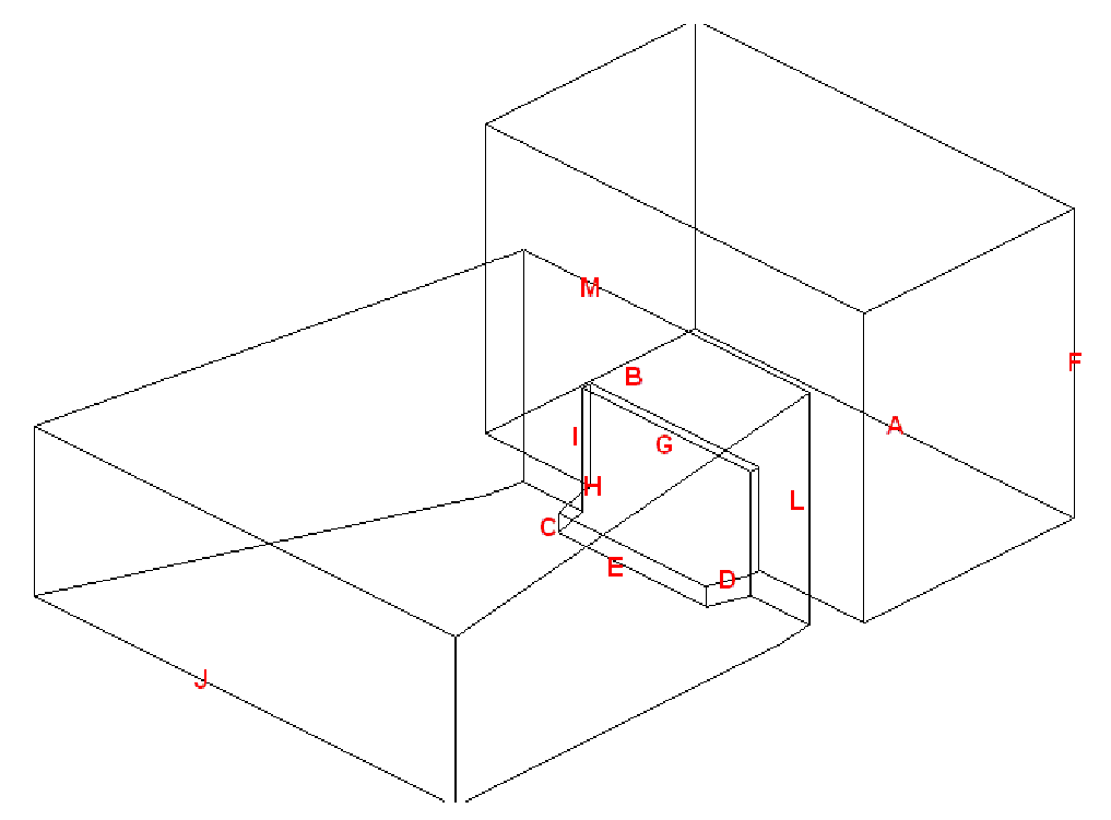

The following entries describe the parts of the proscenium arch.
nA: The stage width; the dimension from the extremity of the SR wing to the extremity of the SL wing. In WYSIWYG, the default value is 90’0”.
nB: The stage depth; the dimension from the proscenium line to the back of the stage space. In WYSIWYG, the default value is 50’0”.
nC: The stage height; the dimension from the auditorium floor to the stage deck. In WYSIWYG, the default value is 4’0”.
nD: The thrust depth; the dimension from the edge of the stage to the proscenium line. In WYSIWYG, the default value is 8’0”.
nE: The thrust width; the dimension from the extremity of the SR edge of the thrust to the SL extremity of the thrust. This dimension cannot be greater than the Arch width (G). In WYSIWYG, the default value is 35’0”.
nF: The Fly height; the dimension from the stage deck to the top of the fly house. In WYSIWYG, the default value is 60’0”.
nG: The proscenium arch width. In WYSIWYG, the default value is 40’0”.
nH: The depth of the proscenium arch wall. In WYSIWYG, the default value is 2’0”.
nI: The height of the proscenium arch; the dimension of the opening of the proscenium arch. In WYSIWYG, the default value is 20’0”.
nJ: The back of house (BOH) width; the dimension of the auditorium from the extremity of house right to the extremity of house left at the back of the house. In WYSIWYG, the default value is 100’0”.
nK: The auditorium depth; the dimension from the proscenium line to the back of the house. In WYSIWYG, the default value is 100’0”.
nL: The auditorium height; the dimension from the ceiling of the auditorium to the floor of the auditorium at the edge of the stage. In WYSIWYG, the default value is 45’0”.
nM: The front of house (FOH) width; the dimension of the auditorium from the extremity of house right to the extremity of house left at the front of the house. In WYSIWYG, the default value is 68’0”.
nN: The auditorium slope height. In WYSIWYG, the default value is 12’0”.
A Black Box venue is an empty rectangular room. The origin is set at the center of the room on the floor.
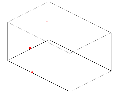
The following entries describe the parts of the black box:
nA: The width of the room. In WYSIWYG, the default value is 60’0”.
nB: The depth of the room. In WYSIWYG, the default value is 40’0”.
nC: The height of the room. In WYSIWYG, the default value is 30’0”.
An Arena venue is a basic stadium space. The following entries describe the parts of the arena. The origin is set at the center of the venue on the floor or ice rink.
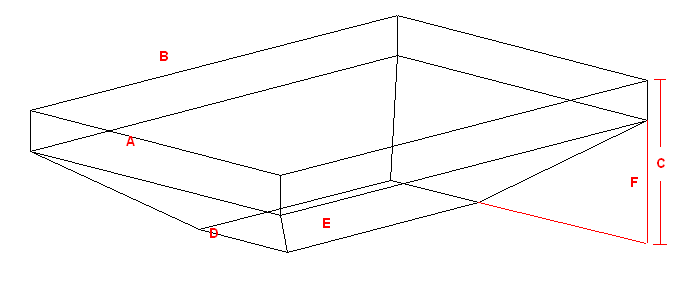
nA: The width of the arena. In WYSIWYG, the default value is 170’0”.
nB: The depth of the arena. In WYSIWYG, the default value is 250’0”.
nC: The total height of the arena. In WYSIWYG, the default value is 60’0”.
nD: The width of the floor or ice rink. In WYSIWYG, the default value is 60’0”.
nE: The depth of the floor or ice rink. In WYSIWYG, the default value is 130’0”.
nF: The height of the stands or seating; the portion of the total height that is occupied by seating or stands. In WYSIWYG, the default value is 40’0”.
There are two types of tents that you can create in WYSIWYG: Frame Tents and Circus Tents.
nFrame Tents: These tents are square or rectangular in shape and usually have two center poles. Each wall is made of a single piece of fabric supported by as many poles as you specify.
nCircus Tents: These tents are styled after the classical “Big Top” of the circus. They are more rounded in shape than the frame tent, the walls comprising multiple sections, each supported by as many poles as you specify. The roof is held up by one center pole.
When drawing either type of tent, you can specify many different properties, including the number of poles, length, height, or perimeter of the walls, and the color of different parts of the tent.
You can also choose from different materials and you can choose whether you want to apply either a custom color or texture to different parts of the tent. When assigning a texture, you can choose your own texture, such as a company logo or symbol, or you can choose a texture from the WYSIWYG library.
The origin for both types of tents is at the center of the tent on the floor.
Frame Tent
The following entries describe the parts of the frame tent:
|
Description |
New Venue - Tent Field |
WYSIWYG Default Value |
|---|---|---|---|
A |
The height of the tent walls. |
Wall height |
20’0” |
B |
The length of the tent walls. |
Width |
80’0” |
C |
The width the tent walls. |
Depth |
70’0” |
D |
The height that the center pole extends above the height of the walls. |
Height above walls |
10’0” |
E |
The distance between the center poles. |
Separation |
20’0” |
Circus Tent
The following entries describe the parts of the circus tent:
|
Description |
New Venue - Tent Field |
WYSIWYG Default Value |
|---|---|---|---|
A |
The number of individual segments in the tent. |
Segments |
6 |
B |
The height of the tent walls. |
Wall height |
20’0” |
C |
The height that the center pole extends above the height of the walls. |
Height above walls |
10’0” |
D |
The diameter of the tent, measured from pole to opposite pole. |
Diameter |
70’0” |
Lines are 2D objects. Lines are drawn continuously, allowing you to create shapes made up of multiple vertices.
Lines come in four pattern styles.
nSolid
nCenter
Line patterns determine how line objects appear on your plot and can be modified at any time. The image below shows how line patterns appear in WYSIWYG.

Line patterns are available to a Rectangle, Circle, Ellipse, Arc or Elliptical Arc, and a Closed Line Polygon.
You can make a multi-vertex line appear as a spline or french curve by selecting the option in the properties box. You can then drag the markers around to adjust the curves. Alternatively, you can choose to draw a spline directly. Splines have the same line style options as regular lines.
Multi-segmented lines
When you draw multi-segmented lines, or add a line to a surface, the next point of the line you wish to add snaps automatically to the previously drawn line/surface’s endpoint, midpoint or intersection when the Endpoint Snap, Midpoint Snap or Intersection Snap are enabled.
Lines can be extruded into surfaces. For information on extruding lines, see “Extrude”.
1From the Draw menu, choose Line.
2From the sub-menu, select Solid, Dot, Center, Dashed, or Spline.
Tip: You can also use the appropriate line tool on the Draw toolbar. The available line tools are as follows:
n ![]() Solid
Solid
n![]() Centered
Centered
n![]() Dashed
Dashed
n![]() Dotted
Dotted
n![]() Spline
Spline
3Click in the wireframe at the starting point of the line.
4Drag the next vertex to its end point and click.
5Continue to place vertices of the line as needed.
6To end the line at its last end point, right-click and choose Finish Line. To abort the line entirely, choose Abort Line. This erases the whole line from the drawing.
To draw a line by specifying coordinates
You can also draw lines using coordinates by specifying absolute or relative values.
1From the Draw menu, choose Line and select Solid, Dot, Center or Hidden.
2In the Command Line, type the absolute X, Y and Z coordinates (separated by commas) where you want the line to start (i.e. 0,0,0).
3Press ENTER to establish the first point of the line.
4In the Command Line, type the absolute X, Y and Z coordinates (separated by commas) where you want the next point of the line.
or,
Using the relative values, in the Command Line, type @, followed by the length towards the next point of the line (positive or negative direction), (i.e. @2’,0,3’).
5Press ENTER to draw the new line segment.
6Continue to type absolute or relative values and press ENTER to draw the next line segments.
7When you are finished drawing the lines, right-click and click Finish Line.
To draw a line by specifying its length and angle
1From the Draw menu, choose Line and select Solid, Dot, Center or Hidden.
2In the Command Line, type the X, Y and Z coordinates (separated by commas) where you want the line to start.
3Press ENTER to establish the first point of the line.
4Type the length towards the next point of the line, followed by the < sign, and the angle (direction), (i.e.3’6”<180).
5Press ENTER to draw the new line segment.
6Continue to type the length and angle in the Command Line.
7When you are finished drawing the lines, right-click and click Finish Line.
Tip: You can also determine the direction of the line from the cursor’s current position relative to the start point set in step 2.
Points are identifiers of a specific coordinate in 3D space. Points are inserted as references or as scenic elements.
To draw a point
1From the Draw menu, choose Point.
Tip: You can also use the Point tool on the Draw toolbar.
|
The Point button. |
2Click on the drawing to place the point.
Note: Points can be drawn as a dot, a cross, a square, or a circle.
To set the point type default
1From the Options menu, choose Document Options.
2Click the Object Settings tab.
3Select the desired point type.
4Click OK.
There are two ways in which you can draw circles:
nNon-interactive mode in which you type the exact horizontal and vertical radius of the circle.
nInteractive mode in which you click and drag to set the radius.
To draw a circle in non-interactive mode
1From the Draw menu, choose Circle.
Tip: You can also use the Circle tool on the Draw toolbar.
|
The Circle button. |
Result: The New Circle dialog box appears.

2In the Horizontal Radius box, type the horizontal radius for the circle. The default value is 4’0”.
3In the Vertical Radius box, type the vertical radius for the circle. The default value is 4’0”.
Notes:
nTo ensure that the circle remains proportionately the same when resized, leave the Lock Ratio checkbox checked. If you clear this checkbox, then you can manually resize the circle in any direction, regardless of its original measurements.
nTo convert the circle into a surface, select the Convert to Surface checkbox.
4Click OK.
5Click on the drawing to place the circle.
6Click elsewhere in the drawing to finish placing the new circle.
To draw a circle in interactive mode
Note: To turn interactive mode on, click the Interactive Mode button on the toolbar.
|
The Interactive Mode button. |
1From the Draw menu, choose Circle.
Tip: You can also use the Circle tool on the Draw toolbar.
|
The Circle button. |
2Click to place the center of the circle.
3Click to set the radius for the circle.
There are two ways in which you can draw arcs:
nNon-interactive mode in which you type the exact radius, start, and end angles of the arc.
nInteractive mode in which you click and drag to set the arc.
To draw an arc in non-interactive mode
1From the Draw menu, choose Arc.
Tip: You can also use the Arc tool on the Draw toolbar.
|
The Arc button. |
Result: The New Circular Arc window appears.

2In the Radius box, type a radius for the arc. The default value is 4’0”.
3In the Start Angle box, type the start angle. The default value is 0.00.
4In the End Angle box, type the end angle for the arc. The default value is 180.00.
5Click OK.
6Click on the drawing to place the arc.
To draw an arc in interactive mode
Note: To turn interactive mode on, click the Interactive Mode button on the toolbar.
|
The Interactive Mode button. |
1From the Draw menu, choose Arc.
Tip: You can also use the Arc tool on the Draw toolbar.
|
The Arc button. |
2Click to place the start point of the arc.
3Click to place the end point of the arc.
4Click to place the middle point of the arc.
5Click elsewhere in the drawing to finish placing the arc.
There are two ways to draw an arc:
nNon-interactive mode in which you specify the elliptical arc radius, start and end angles and place the arc in the drawing.
nInteractive mode in which you draw the elliptical arc.
To draw an elliptical arc in non-interactive mode
1From the Draw menu, choose Elliptical Arc.
Tip: You can also use the Elliptical Arc tool on the Draw toolbar.
|
The Elliptical Arc button. |
Result: The New Elliptical Arc window appears.

2In the Radius box, enter a radius for the elliptical arc. The default value is 4’0”.
3In the Start Angle box, enter the start elliptical angle. The default value is 0.00.
4In the End Angle box, enter the end angle for the elliptical arc. The default value is 180.00.
5Click OK.
6Click and drag the mid point of the arc to create the desired elliptical.
To draw an arc in interactive mode
Note: To turn interactive mode on, click the Interactive Mode button on the toolbar.
|
The Interactive Mode button. |
1From the Draw menu, choose Elliptical Arc.
Tip: You can also use the Arc Elliptical tool on the Draw toolbar.
|
The Elliptical Arc button. |
2Click to place the start point of the elliptical arc.
3Click to set the horizontal and vertical radii of the elliptical arc.
4Click to set the start point of the ellipse.
5Click to set the end point of the ellipse.
There are two ways to draw rectangles:
nNon-interactive mode in which you enter the exact length and width of the rectangle.
nInteractive mode in which you draw the size of the rectangle.
To draw a rectangle in non-interactive mode
1From the Draw menu, choose Rectangle.
Tip: You can also use the Rectangle tool on the Draw toolbar.
|
The Rectangle button. |
Result: The New Rectangle window appears.

2In the Length box, type the length for the rectangle. The default value is 4’0”.
3In the Width box, type the width for the rectangle. The default value is 8’0”.
Tips:
nTo ensure that the rectangle remains proportionately the same when resized, select the Lock Ratio checkbox. Otherwise you can manually resize the rectangle in any direction, regardless of its original measurements.
nTo convert the rectangle into a surface, select the Convert to Surface checkbox.
nTo add hatching to the rectangle, select the Show Hatch Lines checkbox.
4Click OK.
5Click in the drawing to place the rectangle.
To draw a rectangle in interactive mode
Note: To turn interactive mode on, click the Interactive Mode button on the toolbar.
|
The Interactive Mode button. |
1From the Draw menu, choose Rectangle.
Tip: You can also use the Rectangle tool on the Draw toolbar.
|
The Rectangle button. |
2Click to place one corner of the rectangle.
3Click to place the opposite corner for the rectangle.
Polygons are regular shaped objects comprising multiple vertices. You can draw polygons as 2D objects or specify a height value to draw 3D objects. You can use polygons to create either wireframe or solid objects.
Unlike the Surface tool, with the Polygon tool you can quickly and easily create symmetrical shapes like squares, pentagons, hexagons, hectagons, and so on. The maximum number of edges that a polygon can have is 40.
Notes:
nUnlike most other tools, the polygon tool does not have an interactive mode.
nThe size of the polygon can be defined either by specifying the edge length or radius.
To draw a polygon
1From the Draw menu, choose Polygon.
Tip: You can also click the Polygon tool on the Draw toolbar.
|
The Polygon button. |

2In the Number of Edges field, type the number of edges or sides of the polygon.
3Click Edge Length if you want to define the size of the polygon by the length of its edges, and then type the value in the box provided.
4Click Radius if you want to define the size of the polygon by the distance between the center and the vertices or the edges' midpoints, and then type the distance in the box provided.
nClick Circumscribed if you want to define the size of the polygon by the distance between the center and the vertices. This is equal to the radius of the circumscribed circle.
nClick Inscribed if you want to define the size of the polygon by the distance between the center and the edge midpoints. This is equal to the radius of the inscribed circle.
5Click Surface if you want to create the polygon as a surface (i.e., a filled in object to which you can apply a texture, etc.).
6Click Closed Line if you want to create the polygon as a closed line (i.e., a polygon comprised of an outline that is open in the middle).
7Click Height if you want to extrude the polygon into a 3D object, and then type the height value in the box provided.
8Select the Show Hatch Lines checkbox to add hatching lines to the polygon.
9Click OK to place the polygon in your drawing.
Before you draw your text labels in CAD mode, you can select the font that will be used in all labels. You can choose from any font installed on your computer.
To change the text label font globally
You can specify the font that you would like to appear globally in all text labels, both new and existing.
1In any drawing mode, click Options > Document Options.
2Click the Fonts tab.
3Under CAD Text Labels, select the font that you want to appear in all new text labels from the Font drop-down list.
4Choose whether you want the letters to appear bold, underlined, or in italics.
5Click OK.
1From the Draw menu, choose Text Label.
Tip: You can also use the Text Label tool on the Draw toolbar.
|
The Text Label button. |
Result: The New Text Label window appears.

2In the Text box of the New Text Label window, type the desired text.
Notes:
nUse SHIFT+ENTER to add new text lines.
nYou may include text labels containing information listed in the Production Team Information table. Use smart variables “%Variable Name%” in the Text Label box and this information will automatically be displayed if it is stored in the Production Team Information table. For example, type “%Director%” and the name of the Director stored in the table will appear in the Text Label.
3Click Insert Smart Variable to open the Smart Variables window where you can select the smart variable names and values that are listed in the Production Team Info tab in Document Options.
Result: The Smart Variables window appears.
4From the table in the Smart Variables window, click on the name or value that you wish to insert in the text box.
Tip: Select which information to display in the table from the Filter drop-down list. For information on Smart Variables, see “Smart cells”.
5Select the Include Name and Value checkbox to display both texts under the Name and Value columns, or clear the checkbox to display only the texts under the value column.
6Click Insert.
Result: The smart variable text appears in the Text box of the New Text Label window.
7Click Insert Item Data to open the Item Data window, where you can select retrieved catalog name and other information of fixtures and trusses, to insert in your drawing.
The retrieved information are displayed in the Item Data window only after Retrieve Item Data is initiated from the Library > Retrieve Item Data menu in CAD, and then clicking the Fixture or Truss item. See “To retrieve data from a fixture or truss object”.
Result: The Item Data window appears.
8From the table in the Item Data window, click on the row that contains the name and value text that you wish to add into the text box.
9In the Item Data window, you can select the fixture or truss item from the Recent Items drop-down list. The Recent Items drop-down list displays a maximum of five items recently selected.
10Click Insert.
Result: Information from the selected fixture or truss appears in the Text box of the New Text Label window.
11Using the radio buttons, choose how you want to specify the Height of the Text Label, and enter the value in the corresponding field.
nIndividual Line of Text: Each line of text will be the chosen height. The text label will change size to accommodate the height.
nTotal Text Label: The total text box will be the chosen height. Text will change size to accommodate the height.
a.To add space between the text and the border of the text label, select the checkbox next to Text Label Padding, and enter the value of the padding in the field.
Note: The Total Text Label Height field will tell you the exact height of the text label based on your choices.
12To add a callout to the text label, select the Show Callout checkbox.
13From the Position drop-down list, select where the callout will be located on the text label.
14To have an arrow at the end of the callout, select the Show Arrow checkbox.
15To add a border to the text label, select the Show Border checkbox.
16To fill the text label with color, select the Fill checkbox.
a.Click the Color Selector button to choose the color that will fill the text label.
17To align the text label to the current view, select the Align to View checkbox.
18To insert the text label, click OK.
Result: The New Text Label window closes and you will be in the Wireframe view.
Note: If the Callout checkbox was selected in the New Text Label window, the first click in Wireframe view will be the arrow's position, and the second position will place the text label.
19Click on the drawing to place the text label.
Result: The text label will be placed.
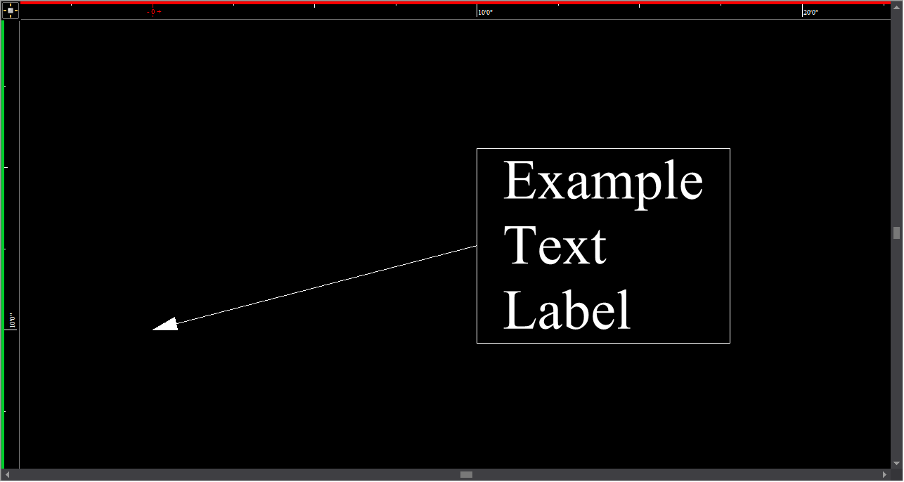
Notes:
nTo change the font of existing text labels in CAD mode, see ““To change the font of text labels”” below.
nThe insertion point for the text label is at the intersection of the crosshairs.
To change the font of text labels
To change the font and appearance (bold, italic, or underline) of existing labels, you can use the label’s Properties window or the CAD Text toolbar. The following procedure outlines how to use the Properties window.
1Select the text label whose font you want to change.
2Right-click, and then choose Properties.
3Click the Text Label tab.
4Under Font, clear the check mark beside Use Document Defaults.
5From the Font drop-down list, select the new font.
6Choose whether you want the letters to appear bold, underlined, or in italics.
7Click OK.
To set alignment for a text label
You can use the alignment buttons on the CAD Text toolbar to align text labels.

1Select the text label that you want to align.
2On the CAD Text toolbar, click the appropriate button to align the text label in the desired position (left, center, right, top, middle, or bottom).
Result: The text label is relocated around the insertion point, based on the options selected.
To retrieve data from a fixture or truss object
1From the Library menu, choose Retrieve Item Data.
2Point the cursor to the fixture or truss you want to select, which highlights the item in orange.
3Click on the fixture or truss item.
Result: The New Text Label window appears.
4In the New Text Label window, you can click Insert Item Data to display in your drawing, the information that you retrieved from the selected fixture or truss.
Dimension lines are 2D objects. They have a start and end point, and measure and display the distance covered based on the measurement mode selected. The measurement modes available are: X, Y, XY, XZ, YZ, and XYZ. The dimension will only be visible in one view type. The view type is set when the dimension is drawn and is dependent on the plot type and workplane in which the dimension is drawn.
There are several types of dimensions available:
nLinear dimensions: These dimensions measure and display the distance covered between two points in your plot, based on the measurement mode selected.
nContinue dimensions: These dimensions display sequential chains of linear measurements that are aligned to the start (base) measurement of the Continue Dimension, always using the last point of the previous measurement as the initial point of the next measurement.
nBaseline dimensions: These dimensions display linear measurements stacked above or below the Base Dimension while maintaining uniform spacing between, always using the first click as the initial coordinate for all subsequent measurements.
nArc length dimensions: These dimensions are used to measure the length of arcs drawn in CAD mode.
nRadial dimensions: These dimensions are used to measure the radius of any circle or arc drawn in CAD mode.
nAngle dimensions: These dimensions measure and display an angle, either between two intersecting lines and objects, or as drawn in Freehand mode.
Note: The properties of dimension objects, such as the arrow type, can be changed in the Dimensions tab under Options > Document Options....
1From the Draw menu, choose Dimensions > Linear Dimension.
Tip: You can also click the Linear Dimension tool on the Draw toolbar.
|
The Linear Dimension button. |
Result: The Select Layer for Dimension dialog box appears.

2In the Select Layer for Dimension dialog box, choose the layer for the linear dimension and select the options for the selected layer.
3Click OK to apply and close the dialog box.
4Click on the drawing to set the dimension start point.
5Right-click to set the measurement mode.
Tip: In measurement mode, you can choose Multiple, which enables you to draw multiple Linear Dimensions, using the last point of the previous measurements as the initial point for the next measurement.
6Click on the drawing to set the dimension end point.
7Click and drag the grab point in the center of the dimension text to drag the text to the correct side of the object, if required.
8Click to set the dimension line.
Notes:
nUse snaps to connect dimensions directly to other objects.
nYou can set the rotation angle of the Linear Dimension to rotate the extension lines around the dimension end points. The rotated Linear dimension will then display the distance between the two points at the angle specified. Right-click on the Linear Dimension and select Properties.
nYou can change the Fill color behind the dimension text of the Linear Dimension. Right-click the Linear Dimension and select Properties.
nYou can enable Display Dash in Document Options > Dimensions tab to display the linear dimensions with a dash between foot and inches in imperial measurements (e.g. 19’-3 11/16”).
nTo adjust the font used in all dimensions, from the Options menu, choose Document Options > Font. In the CAD Dimensions area, select the font options to be used in all dimensions.
To draw a continue dimension
1From the Draw menu, choose Dimensions > Continue Dimension.
Tips:
nYou can also click the Continue Dimension tool on the Draw toolbar.
|
The Continue Dimension button. |
nYou can also start the Continue Dimension on an existing Linear Dimension.
Result: The Select Layer for Dimension dialog box appears.

2In the Select Layer for Dimension dialog box, choose the layer for the continue dimension and select the options for the selected layer.
3Click OK.
Result: The Dimension Draw Options dialog box appears.

4In the Dimension Draw Options dialog box, select the Use Document Defaults checkbox to use the default setting for extension height or clear the Use Document Defaults checkbox and type the custom Extension height for the Continue Dimension.
5Click OK to apply and close the dialog box.
6Click on the drawing to set the dimension start point.
7Click on the drawing to set the next point and direction of the subsequent measurements in the Continue Dimension.
8Repeat setting the next point and direction to continue on the subsequent dimensions.
9Right-click on the drawing to set the dimension end point.
Note: After completing a Continue Dimension, the measurements created are individual Linear Dimensions.
To draw a baseline dimension
1From the Draw menu, choose Dimensions > Baseline Dimension.
Tips:
nYou can also click the Baseline Dimension tool on the Draw toolbar.
|
The Baseline Dimension button. |
nYou can also start the Baseline Dimension on an existing Linear Dimension.
Result: The Select Layer for Dimension dialog box appears.

2In the Select Layer for Dimension dialog box, choose the layer for baseline dimension and select the options for the selected layer.
3Click OK.
Result: The Dimension Draw Options dialog box appears.

4In the Dimension Draw Options dialog box, select the Use Document Defaults checkbox to use the default settings for extension height and spacing size for the baseline dimension. Or you may clear the Use Document Defaults checkbox and type custom values for the Extension height and Spacing Size for the Baseline Dimension.
5Click OK to apply and close the dialog box.
6Click on the drawing to set the dimension start point.
7Click on the drawing to set the end point of the first Baseline Dimension.
8Click on the drawing to set the position (above or below) for the next/subsequent Baseline Dimension.
9Click on the next point to complete the next Baseline Dimension measurement, and set the direction of the subsequent measurement.
10Repeat setting the next point to create the subsequent Baseline Dimensions.
11Right-click on the drawing to set the dimension end point.
Note: After completing a Baseline Dimension, the measurements created are individual Linear Dimensions.
The arc length can be displayed for any arc drawn in CAD mode. Once enabled, the arc length dimension is attached to the arc and automatically updates itself whenever the arc is changed. The dimension is only visible in the view type in which it was drawn.
Although the arc length dimension is attached to the arc, it is a separate entity. Each arc length is individually selectable and has its own properties. Arc length dimensions can be separated onto their own layers, and given their own colors and line weights.
To draw an arc length dimension
1In a CAD wireframe, select the arc for which you want to display an arc length dimension.
2From the Draw menu, choose Dimensions > Arc Length Dimension.
|
The Arc Length Dimension button. |
Tip: To adjust the font used in all dimensions and with the Angle Dimension tool, click Options > Document Options > Font. In the CAD Dimensions area, select the font options to be used in all dimensions and with the Angle Dimension tool.
The radius of a circle/arc is defined as the distance from the center of a circle/arc to its perimeter. The radius can be displayed for any circle or arc drawn in CAD mode. Once enabled, the radial dimension attaches to the circle/arc and automatically updates itself whenever the circle/arc is changed. Note that the dimension is only visible in the view type in which it was drawn.
Although the radial dimension is attached to the arc, it is a separate entity with its own properties and can be individually selected. Radial dimensions can be separated onto their own layers, and given their own colors and line weights.
To draw a radial dimension
1In a CAD wireframe, select the circle/arc for which you want to display a radial dimension.
2From the Draw menu, choose Dimensions > Radial Dimension.
|
The Radial Dimension button. |
Tip: To adjust the font used in all dimensions and with the Angle Dimension tool, from the Options menu, choose Document Options > Fonts. In the CAD Dimensions area, select the font options to be used in all dimensions and with the Angle Dimension tool.
Angle dimension
The Angle Dimension object measures and displays an angle, either in Line Select, between two intersecting lines and objects, or as drawn in Freehand mode.
To draw an angle dimension in line select
1From the Draw menu, choose Dimensions > Angle Dimension.
|
The Angle Dimension button. |
2Choose Line Select from the Dimension Draw Options dialog box.
3Click on the first line segment in the drawing.
4Click on the second line segment in the drawing.
Result: The angle between the two selected lines is displayed.
To draw an angle dimension in freehand
1From the Draw menu, Dimensions sub-menu, select Angle Dimension.
2Choose Freehand in the Dimension Draw Options dialog box.
3Click on the drawing to define the first end point (point number 1 in the diagram above) of the Angle Dimension.
4Click a second time to define the vertex of the angle (this is the point at which the two lines of your angle meet, shown as point number 2 in the diagram above).
5Click a third time to define the second end point (point number 3 in the diagram above).
Result: The new object displays the interior (or exterior) angle defined by the arc between the end points of the Angle Dimension.
Tips:
nYou can change the angle option of measuring the exterior or interior angle by toggling the Flip Angle checkbox in the Angle Dimension Properties page. Simply right-click the Angle Dimension, and choose Properties > Angle Dimension tab.
nTo adjust the font used in all dimensions and with the Angle Dimension tool, click Options > Document Options > Fonts. In the CAD Dimensions area, select the font options to be used in all dimensions and with the Angle Dimension tool.
A Linear Scale is a visible line divided into equal proportions used to compare distances in WYSIWYG wireframe to actual distances.
To draw a linear scale
1From the Draw menu, choose Dimensions > Linear Scale.
|
The Arc Length Dimension button. |
Result: The New Linear Scale window appears.

2In the Length field, enter in the desired length of the linear scale.
3Select either Horizontal or Vertical to determine how the line scale is positioned.
4From the Text Alignment drop-down list, choose how the linear scale text will be presented.
5From the Layer drop-down list, choose in which layer the linear scale will be visible.
nSelecting the checkbox next to Show non-editable layers (indicated by *) will show non editable layers in the Layer drop-down list.
6To change the default document settings of the linear scale, clear the checkbox next to Use Document Defaults.
7Click OK.
Result: The linear scale is attached to the cursor.
8Click to place the linear scale in the drawing.
When Auto Truss Dimension is applied, truss objects that are selected in the drawing will be displayed with linear dimensions automatically, and with the option of showing values that were set in Truss Manager or the default values from the Library. See “Truss Manager”.
To apply auto truss dimension
1In Wireframe, select the truss object(s).
2From the Draw menu, choose Dimensions > Auto Truss Dimension.
Result: The Select Layer for Dimension dialog box appears.
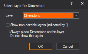
3Select the layer and the options in the Select Layer for Dimension dialog box.
4Click OK.
Result: The Auto Truss Dimension window appears.

5Select the Use Truss Manager Values checkbox to apply the values that were set in Truss Manager or select Use Measured Truss Values to apply manually applied linear dimensions.
6Select the checkboxes for Dimension X, Dimension Y, and/or Dimension Z to specify which dimensions of a truss to add into your drawing.
7Click Open Truss Manager to launch Truss Manager.
8Click OK.
Result: The truss object(s) that were selected in your drawing are displayed with the linear dimensions showing the values set in Truss Manager if Use Truss Manager Values was selected. The manually applied linear dimension values will be displayed if Use Measured Truss Values was selected.
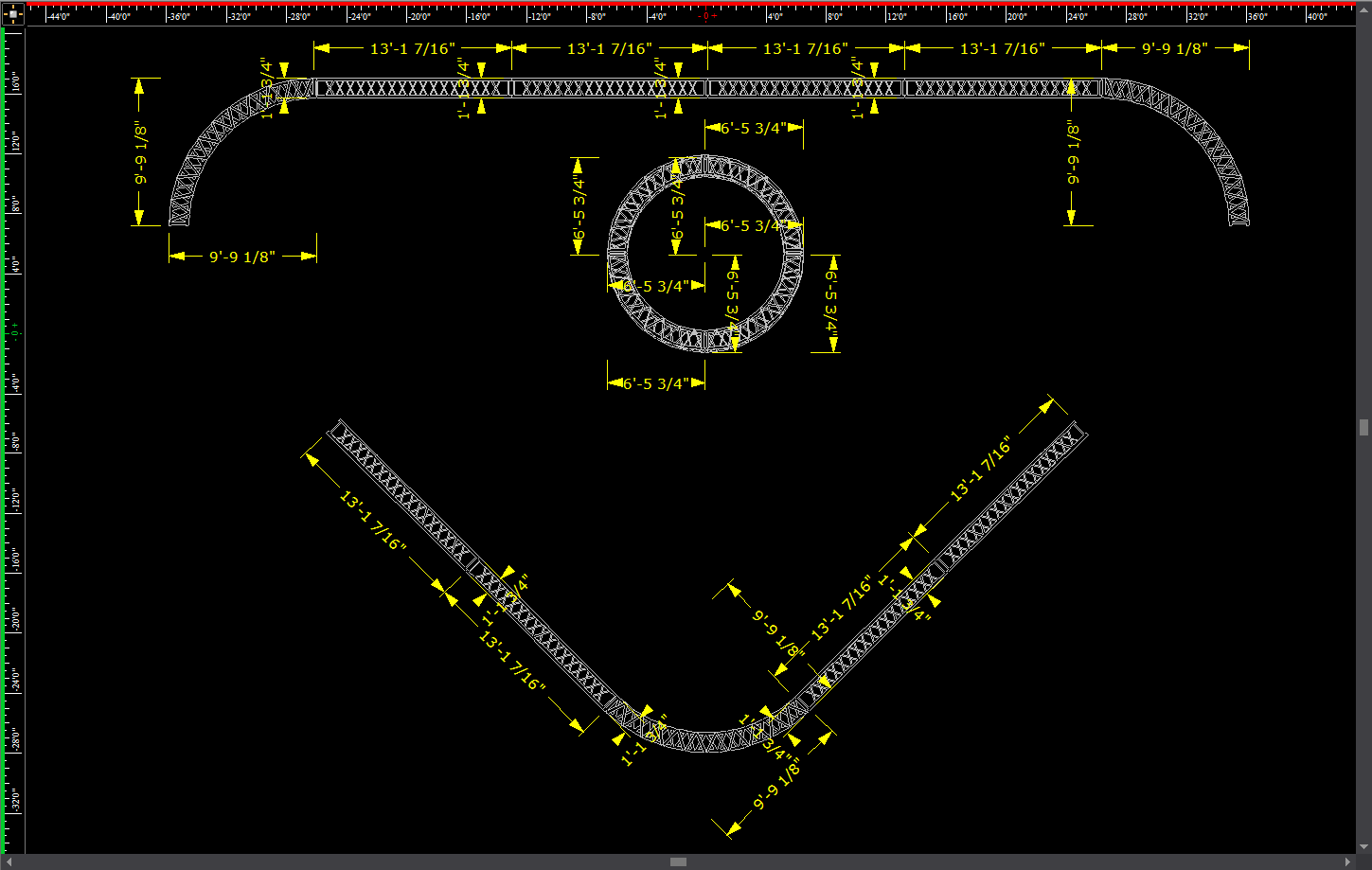
Surfaces are 2D objects. Surfaces are drawn continuously, stretching out behind the cursor and can be used to create backdrops or other flat objects. Surfaces can be extruded to create odd shaped risers, or other custom shaped 3D objects. For more information on extruding, see “Extrude”.
When you draw multi-segmented lines or surfaces, the new line or surface snaps automatically to the previously drawn line or surface's endpoint, midpoint or intersection when the Endpoint Snap, Midpoint Snap or Intersection Snap are enabled.
Note: The beam will pass through a surface with the Transparency value set to 80% or greater. The beam will not pass through the surface when the value is lower than 80%. Transparency value is set in the Material Properties section in the Appearance tab of the Properties window. Refer to “Appearance tab”.
To ensure that textures, if any, are applied properly, the surface must be drawn in a counter-clockwise direction.
1From the Draw menu, choose Surface.
Tip: You can also click the Surface tool on the Draw toolbar.
|
The Surface button. |
2Click on the drawing at the starting point of the surface.
3Moving in a counter-clockwise direction, drag to the next point of the surface and click.
4Continue to place points for the surface as needed, always moving counter-clockwise. In the following graphic, the starting point is labelled A:
5To finish and close the surface, right-click and choose Finish Surface from the sub-menu. To abort the surface entirely, choose Abort Surface. This erases the whole surface from the drawing.
Vertical surfaces can have their appearance changed to mimic the look of curtains in 2D Plan View. The curtain will appear as a wave or semicircles pattern, instead of the usual straight line of a surface. The depth, width and number of segments in the curtain pattern can be customized.

Note: Curtains are limited to being visible only in 2D Plan View, with a surface that is vertical and rectangular in shape, with no surface area visible in Plan View.
To display a surface as a curtain.
1Right-click an eligible surface and select Properties.
2In the Properties window, click the Surface tab.

3To enable the curtain feature for the surface, select the checkbox labeled Enable.
Note: If the surface is ineligible to be a curtain, this option will be greyed out.
4From the Style drop-down list, select which pattern of curtain should be displayed.
5Enter the desired depth of the curtain pattern in the Depth field.
6Enter the desired width of the curtain pattern in the Width field.
7Enter the desired number of segments in the curtain pattern in the Number of Segments field.
8Click Apply.
Walls are 2D objects that describe flat rectangular planes representing walls in your drawing. Walls can have different hatching styles for easy identification in the plot.
There are two ways to draw a wall:
nNon-interactive mode in which you specify the width and height and place the wall in the drawing.
nInteractive mode where you draw the wall freehand.
To draw a wall in non-interactive mode
1From the Draw menu, choose Wall.
Tip: You can also click the Wall tool on the Draw toolbar.
|
The Wall button. |
Result: The New Wall window appears.

2In the Width box, enter the width for the wall. The default value is 12’0”.
3In the Height box, enter the height of the wall. The default value is 8’0”.
4In the Thickness box, enter the thickness of the wall. The default value is 0'6"
5To enable hatching for the object, select the Show Hatch Lines checkbox.
6Select the desired hatching style for the object from the Hatch Style drop-down list.
7Click OK.
Result: The wall attaches to the cursor.
8Move the cursor to the desired position for the wall, and then click to place it in the drawing.
To draw a wall in interactive mode
Note: To turn interactive mode on, click the Interactive Mode button on the toolbar.
|
The Interactive Mode button. |
1From the Draw menu, choose Wall.
2Click to place the start point of the wall.
3Click to place the end point of the wall.
4In the dialog box that opens, enter the missing dimension of the wall.
5Click OK.
To define the transparency of a wall
1Right-click a wall, and select Object Properties.
Result: The Properties window appears.
2In the Properties window, click the Wall tab.

Note: 0% = Opaque, 100% = Transparent.
3To change how the back of the wall will look, set the Back Transparency field to the desired transparency percentage.
4To change how the front of the wall will look, set the Front Transparency field to the desired transparency percentage.
5Click Apply to enable the new wall transparency settings.
6Click OK.
Risers are solid 3D rectangular objects. You can use risers for creating platforms, square columns, or any other box-shaped objects.
There are two ways in which you can draw risers:
nNon-interactive mode in which you type the exact width, depth, and height of the riser.
nInteractive mode in which you click and drag to set the dimensions of the riser.
To draw a riser in non-interactive mode
1From the Draw menu, choose Riser.
Tip: You can also click the Riser tool on the Draw toolbar.
|
The Riser button. |
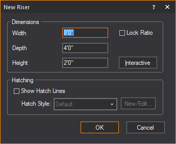
Note: To ensure that the riser remains proportionately the same when resized, leave the Lock Ratio checkbox checked. If you clear this checkbox, then you can manually resize the riser in any direction, regardless of its original measurements.
2In the Width box, type the width for the riser. The default value is 8’0”
3In the Depth box, type the depth for the riser. The default value is 4’0”.
4In the Height box, type the height for the riser. The default value is 2’0”.
5To enable hatching for the object, select the Show Hatch Lines checkbox.
6Select the desired hatching style for the object from the Hatch Style drop-down list.
7Click OK.
Result: The riser is attached to the cursor.
8Drag the new riser to its position, and then click to place it in the drawing.
To draw a riser in interactive mode
Note: To turn interactive mode on, click the Interactive Mode button on the toolbar.
|
The Interactive Mode button. |
1From the Draw menu, choose Riser.
2Click the starting point of the riser on the drawing. The insertion point is the lower left corner of the riser.
3Drag in any direction to stretch out the riser’s shape. Click to place the upper right corner of the riser.
4In the dialog box that opens, type the missing dimension of the riser.
5Click OK.
Note: You can now snap to all eight points on a riser: top corners and bottom corners.
Cylinders are solid 3D objects. Cylinders can be used for creating platforms, columns, or any other cylinder-shaped objects.
There are two ways in which you can draw cylinders:
nNon-interactive mode in which you type the exact height and radius of the cylinder.
nInteractive mode in which you click and drag to set the dimensions of the cylinder.
1From the Draw menu, choose Cylinder.
Tip: You can also click the Cylinder tool on the Draw toolbar.
|
The Cylinder button. |
Result: The New Cylinder window appears.

2In the Height box, type the height for the cylinder. The default value is 8’0”.
3In the Horizontal Radius box, type the horizontal radius for the cylinder. The default value is 4’0”.
4In the Vertical Radius box, type the vertical radius for the cylinder. The default value is 4’0”.
5To ensure that the cylinder remains proportionately the same when resized, leave the Lock Ratio checkbox checked. If you clear this checkbox, then you can manually resize the cylinder in any direction, regardless of its original measurements.
6To have the cylinder appear smooth in the Shaded view, leave the Smooth Shading option enabled; to see a faceted cylinder in the Shaded view, disable this option. The default for this option is ON.
7To change the default number of cylinder segments, clear the checkbox beside Use Defaults and type the new number of segments. Note that the higher the number of segments, the better the cylinder will appear in Shaded view, but the more performance will degrade.
8To enable hatching for the object, select the Show Hatch Lines checkbox.
9Select the desired hatching style for the object from the Hatch Style drop-down list.
10Click OK.
Result: The cylinder is attached to the cursor.
11Drag the new cylinder to its position, and then click to place the object in the drawing.
To draw a cylinder in interactive mode
Note: To turn interactive mode on, click the Interactive Mode button on the toolbar.
|
The Interactive Mode button. |
1From the Draw menu, choose Cylinder.
2Click to place the center of the bottom surface of the cylinder.
3Click to set the radius for the cylinder.
4In the dialog box that opens, type the desired height, horizontal radius and vertical radius for the cylinder.
5To ensure that the cylinder remains proportionately the same when resized, leave the Lock Ratio checkbox checked. If you clear this checkbox, then you can manually resize the cylinder in any direction, regardless of its original measurements.
6To have the cylinder appear smooth in the Shaded view, leave the Smooth Shading option enabled; to see a faceted cylinder in the Shaded view, disable this option. The default for this option is ON.
7To change the default number of cylinder segments, clear the Use Defaults checkbox and type the new number of segments. Note that the higher the number of segments, the better the cylinder will appear in Shaded view, but the more performance will degrade.
8Click OK.
Spheres are solid 3D circular or oval objects.
There are two ways in which you can draw spheres:
nNon-interactive mode in which you type the exact horizontal radius, depth radius and vertical radius of the sphere.
nInteractive mode in which you click and drag to set the dimensions of the sphere.
To draw a sphere in non-interactive mode
1From the Draw menu, choose Sphere.
Tip: You can also click the Sphere tool on the Draw toolbar.
|
The Sphere button. |
Result: The New Sphere window appears.

2In the Horizontal Radius box, type the horizontal radius for the middle of the sphere.
3In the Depth Radius box, type the depth radius for the middle of the sphere.
4In the Vertical Radius box, type the vertical radius for height of the middle of the sphere.
5To ensure that the sphere remains proportionately the same when resized, leave the Lock Ratio checkbox checked. If you clear this checkbox, then you can manually resize the sphere in any direction, regardless of its original measurements.
6To change the default number of sphere segments and stacks, clear the Use Defaults checkbox and type the new values for Number of Segments and Number of Stacks. Note that the higher the number of segments or stacks, the better the sphere will appear in Shaded view, but the more performance will degrade.
7To have the sphere appear smooth in the Shaded view, leave the Smooth Shading option enabled; to see a faceted sphere in the Shaded view, disable this option. The default for this option is ON.
8Click OK.
Result: The sphere is attached to the cursor.
9Click to place the sphere in the drawing.
To draw a sphere in interactive mode
1From the Draw menu, choose Sphere.
Tip: You can also click the Sphere tool on the Draw toolbar.
|
The Sphere button. |
2In the New Sphere window, click Interactive.
3Click and drag out the shape of the sphere in your drawing. When you have the desired size, click again.
Result: The New Sphere window appears again.
4In the New Sphere dialog box, you can change the default Horizontal Radius, Depth Radius, and Vertical Radius of the new sphere.
5To ensure that the sphere remains proportionately the same when resized, leave the Lock Ratio checkbox checked. If you clear this checkbox, then you can manually resize the sphere in any direction, regardless of its original measurements.
6To change the default number of sphere segments and stacks, clear the Use Defaults checkbox and type the new values for Number of Segments and Number of Stacks. Note that the higher the number of segments or stacks, the better the sphere will appear in Shaded view, but the more performance will degrade.
7To have the sphere appear smooth in the Shaded view, leave the Smooth Shading option enabled; to see a faceted sphere in the Shaded view, disable this option. The default for this option is ON.
8Click OK.
Cones are solid 3D objects.
There are two ways in which you can draw cones:
nNon-interactive mode in which you type the exact horizontal and vertical radius of the cone.
nInteractive mode in which you click and drag to set the dimensions of the cone.
To draw a cone in non-interactive mode
1From the Draw menu, choose Cone.
Tip: You can also click the Cone tool on the Draw toolbar
|
The Cone button. |
.
Result: The New Cone window appears.

2In the Height box, type the height of the cone.
3In the Horizontal Radius box, type the horizontal radius for the cone.
4In the Vertical Radius box, type the vertical radius for the cone.
5To ensure that the cone remains proportionately the same when resized, leave the Lock Ratio checkbox checked. If you clear this checkbox, then you can manually resize the cone in any direction, regardless of its original measurements.
6To change the default number of cone segments and stacks, clear the Use Defaults checkbox and type the new values for Number of Segments and Number of Stacks. Note that the higher the number of segments or stacks, the better the cone will appear in Shaded view, but the more performance will degrade.
7To have the cone appear smooth in the Shaded view, leave the Smooth Shading option enabled; to see a faceted cone in the Shaded view, disable this option. The default for this option is ON.
8To enable hatching for the object, select the Show Hatch Lines checkbox.
9Select the desired hatching style for the object from the Hatch Style drop-down list.
10Click OK.
Result: The cone is attached to the cursor.
11Click to place the cone in the drawing.
To draw a cone in interactive mode
1From the Draw menu, choose Cone.
Tip: You can also click the Cone tool on the Draw toolbar.
|
The Cone button. |
2In the New Cone window, click Interactive.
3Accept the default values, and then click and drag out the shape of the cone in your drawing. When you have the desired size, click again.
Result: The New Cone window appears again.
4In the dialog box that opens, type the height and the horizontal and vertical radius of the new cone.
5To ensure that the cone remains proportionately the same when resized, leave the Lock Ratio checkbox checked. If you clear this checkbox, then you can manually resize the cone in any direction, regardless of its original measurements.
6To change the default number of cone segments and stacks, clear the Use Defaults checkbox and type the new values for Number of Segments and Number of Stacks. Note that the higher the number of segments or stacks, the better the sphere will appear in Shaded view, but the more performance will degrade.
7To have the cone appear smooth in the Shaded view, leave the Smooth Shading option enabled; to see a faceted cone in the Shaded view, disable this option. The default for this option is ON.
8To enable hatching for the object, select the Show Hatch Lines checkbox.
9Select the desired hatching style for the object from the Hatch Style drop-down list.
10Click OK.
11Click in the drawing to finish placing the new cone.
For information on drawing pipes and curved pipes, see “Drawing pipes” in the “Hang Structures” section.
For information on drawing rigging points, see “Drawing rigging points” in the “Hang Structures” section.
For details on drawing focus objects, such as focus positions, focus lines and focus arcs, see “Focus objects”in the “Hanging and focusing fixtures” section.
You can draw a screen and then attach an image or video source or subsource to it.
Tip: To achieve the best visualization of screen projections in Shaded view, enable Global Illumination and select Approximation Method 2 on the Visual Effects tab of the View Options window in Shaded view.
1From the Draw menu, choose Screen.
|
The Screen button. |
Result: The New Screen window appears.
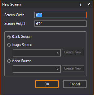
2In the appropriate fields, enter the width and height of the screen.
3To configure the image that will appear on the screen, click the appropriate option button:
nTo leave the screen blank, click the Blank Screen option button.
nTo show a static image on the screen, follow the procedures in the Image Manager section. For details, see “Image Manager”.
nTo attach a video source to the screen, click the Video Source option button, and from the drop-down list, choose the video source or video subsource, or an I-Mag screen from a WYSIWYG Camera, (or click Create New to configure a new video source with the Video Manager). For details on creating a new video source, see “To configure a new video source for streaming video”. For details on splitting video into subsources, see “To create a single video subsource”. For details on creating an I-Mag Camera source, see “To create an I-Mag camera in the Video Manager”.
4Click OK.
Result: The screen is placed into the drawing.

Creating video walls with screens
After a screen has been created, the Grid Array tool can be applied to build a video wall. Applying Grid Array opens the Quick Image/Video Tool where you can set the video/image sources to the screen panels that were created.
To create video walls with screens
1In Front or Back view in Wireframe, select the screen.
2From the Tools menu, choose Array > Array Grid.
Result: The Grid Array window appears.
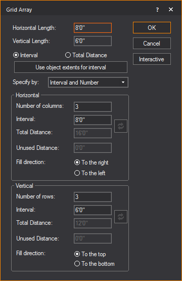
3In the Grid Array window, modify the settings as desired. Refer to “Array” for information on Grid Array settings.
4Click OK.
Result: The Quick Image/Video Tool appears.
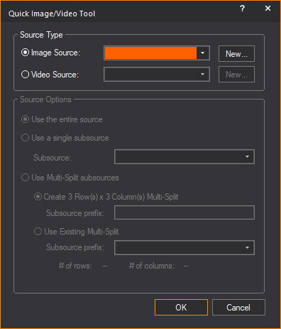
5In the Quick Image/Video Tool window, specify the video or image sources and subsources for the video wall that was created.
6Click OK.
Result: The video wall is created with the video or image applied to the individual screens.
Notes:
nThe Quick Image/Video Tool can be applied to previously drawn screen files, if re-arranged into rows and columns that WYSIWYG can recognize and automatically apply subsources to the individual screens.
nThe Quick Image/Video Tool can be applied to missing panels in the video wall if WYSIWYG can recognize the arrangement of rows and columns.
nThe functionality of the Quick Image/Video Tool remains available if no screens are selected.
After a screen has been created, the properties of a screen can be altered from the properties menu. The following properties of the screen can be changed:

Dimensions and Options: The size of the screen can be changed from its original dimensions and the option to display the source on the front side.
nScreen Width: The width of the screen.
nScreen Height: The height of the screen.
nOnly Display Image/Video on Front Face: Select this checkbox to set the color, Image Source, or Video Source to appear only on the front side of the screen.
Note: The front side of a Screen is the one which does not display the “V” symbol when the Screen appears in Wireframe set to Plan view.
Tip: The Only Display Image/Video on Front Face option will help when using the Global Illumination with Approximation Method 2 Visual Effect; when this Visual Effect is enabled, the illumination it produces will only appear on the front side of the Screen.
Display Source: Options for controlling what will be visible on the screen.
nDisplay Source: Drop-down list for selecting what will be visible on the screen.
nImage Source: Available images that can be displayed on the screen.
nVideo Source: Available videos that can be displayed on the screen.
nKeep Aspect Ratio: Toggle whether to have images/videos displayed on the screen maintain their aspect ratio or stretch/constrict when the size of the screen changes.
nReassign Video/Image Subsource(s): This checkbox is available when the screen is set with Multi-split subsources. Select this checkbox to open the Reassign Video/Image Subsource dialog box and reassign the video and image source types and options for the screen.
Glow Settings: Setting for controlling the glow of the selected screen, independent of the global settings.
Note: The glow effect will appear only on the screen’s front face if Only Display Image/Video on Front Face is selected.
nHide: Toggle to enable/disable the screen glow feature.
nGlow Intensity Multiplier: When enabled can enhance the glow of the screen on a scale of 0 to 10.
You can add cameras to the drawing to provide additional view points in Shaded views and renderings. Place cameras at specific locations, for example, at the Front of House, at extreme Audience Left/Right (to check sightlines), at IMAG camera locations, or camera placement to shoot the show in real-time.
For tips on moving your cameras, see “Camera controls”.
To insert a camera
The following procedure outlines how to insert a camera in a Wireframe view. For information on creating a camera directly from the Shaded view, see “To create a camera from shaded view”.
1From the Draw menu, choose Camera > Camera.
Result: The New Camera properties dialog box appears.
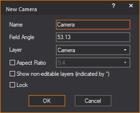
2Type a name for the camera and a value in degrees for the field angle. The default value for the field angle is 53.13.
3From the Layer drop-down list, select the layer of your file on which you want to draw the camera. By default, the Camera object is inserted on the Camera layer.
Note: If you do not see all layers in the Layer drop-down list, click Show non-editable layers.
4(Optional) Select the Aspect Ratio checkbox to set a fixed Aspect Ratio for the new camera. From the Aspect Ratio drop-down list, select the fixed Aspect Ratio for the new camera.
Result: The Shaded view will be defined by the set Aspect Ratio of the selected Camera, with pillar or letter bars displayed to indicate the viewing definition boundaries.
5(Optional) Select the Lock checkbox to lock this new camera in its position and view angle in Shaded view.
6Click OK to apply the settings or Cancel to discard.
7Click on the drawing to place the camera.
8Drag the cursor to aim the camera, and then click to place the target.
Result: The camera is inserted into your drawing and available in the camera selection list for Shaded views and renderings.
Tip: Use the missing coordinate tool while placing the camera and target.
Note: The target of your camera is easily identifiable in Wireframe views as defined by the marker points of the camera drawing. Camera drawings are invisible in Shaded views because you are looking through the camera. For this reason, in this view you can choose to display the target. For more information on displaying the target, see “Modifying shaded views” or “Using the camera toolbar”.
To view or edit camera properties
1In CAD, DESIGN, or LIVE mode, click the Quad or Shaded tab.
2Right-click on the toolbar area and select Camera.
Result: The Camera toolbar appears.
3From the Current Camera drop-down list, select the camera whose Properties you want to view.
4On the Camera toolbar, click the Camera Properties button.
5In the window that appears, you can change any of the following properties:
nName: You can edit the name that appears on the Camera toolbar for the selected Camera.
nField Angle: You can change the field angle of the currently selected Camera, measured in degrees.
nAssigned Hotkey: Click to assign a new numbered hotkey for this Camera. This is the number that you can press from your Number pad to instantly switch from one Camera to the next.
nAspect Ratio: Select this checkbox and choose a fixed Aspect Ratio for the selected Camera.
nLock camera in Shaded View: Select this checkbox to lock the selected camera in its current position in all Shaded views. To unlock it, simply select the camera from the Camera toolbar, and then press the Camera Lock button.
DMX Patch: In this section, you can assign a DMX value to the camera when the Assigned Hotkey is set to None. Select a value from the Assigned DMX Value drop-down list.
Note: When a hotkey of 1-9 is assigned, the DMX value matching the hotkey number is automatically assigned.
nDMX Patch enables the DMX control of the switching between Cameras in LIVE mode, instead of using the drop-down list on the Camera toolbar or the numpad hotkeys.
nAssigned DMX Value drop-down list goes from #10-255 (#1-9 are reserved for hot key assignments).
nWhen the camera has an assigned hotkey, the Assigned DMX Value drop-down list will display the hotkey value as read-only.
nEnable DMX Control of Cameras/Camera Paths must be enabled in the Camera Manager window to enable DMX control of the cameras. Refer to “Camera Manager”.
Camera Paths allow you to define a path along which the camera will travel during playback in the Shaded view, either in DESIGN or LIVE Modes. You draw Camera Paths in CAD Mode just as you would draw a spline. Each point along the path is called a “Node”.
Note: You can keep the Camera Path, nodes and targets visible during file editing, and once you’re done, go into the Properties of these objects and toggle their visibility off in Shaded view.
To draw a camera path
1In Wireframe view, from the Draw menu, choose Camera > Camera Path.
2Click in your plot where you want to start drawing the Camera Path.
3Continue clicking in your drawing to create your path. When you are finished, right-click and select one of the options on the pop-up menu:
nFinish Camera Path: This option finishes the path at the last point, and places it in your plot.
nClose Camera Path: This option closes the path from one end to the next, and places the path in your plot.
nAbort Camera Path: This option cancels the drawing of the Camera Path altogether.
nRemove Last Step: This option removes the last point of the path.
Note: Camera Paths are controlled from DESIGN and/or LIVE modes, using the Camera Path Editor and the Timeline tool. For details, see “Using the Camera Path Editor”.
Camera Paths have unique properties, as shown below:

nName: Camera Paths can have unique names
Shaded View Options
nShow Camera Path in Shaded Views: This option shows or hides the Camera Path in Shaded views while playing the path.
nUse Layer Rendering Color: This option controls the color of the Camera Path and its Layer behavior.
nShow Nodes: This option shows or hides the Nodes along the Camera Path.
nShow Node Numbers: This option shows or hides the Node numbers along the Camera Path.
CAD Options
nClosed: If checked, this option enables the Camera Path to play as a continuous loop with no gaps.
nTension: A value between 0 and 1, where 0 is no tension and 1 is maximum tension; this option enables the Camera Path to allow curving between nodes along the path. If the Tension is set to 0, the nodes will be connected with straight lines.
nCamera Path Arrow - Size: This option allows you to control the size of the direction arrows on the Camera Path.
Patch
nNone: Select this option if the Camera Path is not patched.
nDMX Patch: Select this option if the Camera Path is patched, and then enter the patch properties.
nAspect Ratio: This option allows you to select a fixed Aspect Ratio for this Camera Path.
After you draw a Camera Path, you can also insert a “Camera target” at points of interest where you would like the camera to focus while traveling along a path.
Note: You can keep the Camera Path, nodes and targets visible during file editing, and once you’re done, go into the Properties of these objects and toggle their visibility off in Shaded view.
To draw a camera target
1In Wireframe view, from the Draw menu, choose Camera > Camera Target.
2Type a descriptive name for the camera target.
3Click OK and then click to place the target along the Camera Path.
Camera targets also have unique properties, as seen below:

nLabel: Camera targets can have unique labels.
nHeight: This controls the height of the text associated with the Camera Target.
nAlign to View: This option aligns the target to the specific view that it is in (i.e., Side, Front, Back, Iso)
nShow Label: This option shows or hides the Camera Target label text.
Shaded View Options
nShow in Shaded Views: This option shows or hides the Camera Target in Shaded views while playing the path.
nUse Layer Rendering Color: This controls the color of the Camera target and its Layer behavior.
Text Justification: This section controls the Horizontal and Vertical alignment of the text associated with the Camera Target.
nX, Y, and Z Coordinates: These options allow you to control the position in 3D space of the Camera Target.
Font: This section displays options that allow you control of the font face of the Camera Target. Settings in Document Defaults are used by default.

You can add a compass to a drawing to define the direction that is north. This definition is important to set the position of the sun and/or moon for renderings and Shaded views that use environmental options.
Note: There can be only one compass in a file.
1From the Tools menu, choose Define North.
2Click to place the starting point of the compass.
3Click to place the end point of the compass. The end point must be directly north of the start point.
Result: A compass is drawn, centered on the start point and pointing towards the end point.
Notes:
nTo remove the compass from the drawing, choose Clear Direction from the Tools menu.
nTo redefine north, repeat steps 1-3. You do not need to remove the compass from the drawing when redefining north as there can be only one compass in a file.
For every motion axis that you draw in CAD mode, you can attach one or more objects to it, and then define the object’s position along the axis. You can attach objects such as risers, library objects, or custom objects that you have drawn.
To be able to move an object in different planes, you can attach multiple motion axes to one another. Simply attach the object to one of the axes, and then control the object’s movement along any of the axes by selecting it with the Moving Scenery Designer tool. This feature is useful, for example, if you have a set piece that needs to be able to move in both a vertical and horizontal motion.
Notes:
nWhen attaching axes to one another, you cannot create a circular linking pattern. For example, you can link Axis A to Axis B, and then link Axis B to Axis C, but you cannot then link Axis C back to Axis A because this creates a circular link.
nYou cannot attach fixtures to motion axes; however, you can attach pipes that hold fixtures to axes.
nCurrently, you cannot attach focus positions or groups containing focus positions to motion axes. However, in future releases you will be able to attach either of these items to motion axes.
You can draw axes either diagonally or straight along any direction of movement—X, Y, or Z—choosing between the following two main types of axes:
nLinear: Choose this type of axis to have an object move in a straight line along the path that you specify (or in a series of straight segments all joined together at different vertices to create the path). You can create a linear axis in any length or shape that you require, as long as it comprises straight line segments; you cannot draw a curved axis. For example, you could have a person walk across a stage in a zig zag path, if desired.
When you draw this type of axis, and then attach an object to it, the distance from the axis to the object does not affect the object’s movement; the object will always follow the path of the axis regardless of where you have placed the axis or object.
By default, all linear axes are displayed in your drawing with the label name, and shows an arrow on one end, signaling the direction in which the object will move. In the Properties page, the axes names are displayed with the prefix “[AX-L] to identify a Linear axis.
You can change the name placement and adjust the size of the arrow by opening the Properties page for the axis.
nRotation: Choose this type of axis if you want to have an object rotate in a circular motion. When you click to place this type of axis in your drawing, a circle with a center dot appears. The circle acts as a visual cue, telling you the direction in which the object will rotate; the center dot is the actual axis around which the object rotates.
The orientation of the object’s rotation changes based on the view in which you draw the axis (plan, side, or front/back). When placing the object to be rotated in your drawing, note that its position relative to the center dot of the rotation axis is important. The distance from the center dot to the object represents the size of the circle in which it will rotate, with the dot marking the center of the circle. To have the object rotate in a very tight circle (for example, a dancer doing a pirouette, or a spinning object), place the object directly on the center dot.
By default, all rotation axes are displayed in your drawing with the label name, and shows an arrow on one end, signaling the direction in which the object will rotate. You can change the name placement by opening the Properties page for the axis. In the Properties page, the axes names are displayed with the prefix “[AX-R]” to identify as Rotation axis. While you cannot adjust the size of the arrow head directly, you can click and drag the circle to the desired size, which adjusts the arrow head proportionately. To change the direction of the object’s rotation, switch views, and then drag the center point to the new orientation.
1In Wireframe view, select the view in which you want to draw the axis (plan, front, back, side, or isometric).
2From the Draw menu, choose Axis > Linear Axis.
3In the window that appears, type a name for the axis, and then click OK.
4In your drawing, click in the position where you want to start the axis, and then move your cursor to the next point of the axis and click. To create an axis with multiple segments, continue clicking at each point (vertex) of the axis.
5When you are finished creating the axis, right-click and choose Finish Axis.
To draw a rotation motion axis
Unlike linear axes, rotation axes cannot have multiple vertices. Instead, when you draw one of these axes, the object rotates around the center point.
1In Wireframe view, select the view in which you want to draw the axis (plan, front, back, side, or isometric).
2From the Draw menu, choose Axis > Rotation Axis.
3In the window that appears, type a name for the axis, and then click OK.
4In your drawing, click in the position where you want the axis to appear.
Note: The circle that appears when you draw a rotation axis is only a visual cue to show you the direction in which the object rotates—it does not affect the size of path on which the object rotates. The circle is given a default size, but you can change it to suit your needs.
To patch a motion axis to a DMX universe
To move the object with a DMX control, you first have to attach the motion axis to a named DMX patch universe that you have created in DATA mode.
Note: For information on creating a patch universe, see “To create a new patch universe”.
1Click to select the axis that you want to attach to the patch universe.
2Right-click and select Properties.
3Click the Axis tab.
4From the Patch Type drop-down list, select DMX Patch.
5From the Universe drop-down list, select the DMX patch universe to which you want to attach the axis.
6In the Address box, type the starting DMX address.
7Click OK.
To patch a motion axis to a motion universe
To move the object with a motion control system, you first have to attach the motion axis to a named motion control patch universe that you have created in DATA mode.
Note: For information on creating a patch universe, see “To create a new patch universe”.
1Click to select the axis that you want to attach to the patch universe.
2Right-click and select Properties.
3Click the Axis tab.
4From the Patch Type drop-down list, select Motion Patch.
5From the Universe drop-down list, select the motion control patch universe to which you want to attach the axis.
6From the ID drop-down list, select the ID on the motion control system with which you want to associate this axis.
Note: The motion control system must be connected to your computer for the ID to appear in this drop-down list. If the system is not currently connected, you can also type the ID directly into this drop-down list.
7Click OK.
To attach an object to a motion axis
Notes:
nYou can attach one or more objects to each axis; however, each object can be attached to only one axis at a time.
nWhen you attach an object to a linear axis, the distance from the axis to the object does not affect the object’s movement; the object will always follow the path of the axis regardless of where you have placed the axis or object.
nWhen placing the object to be rotated in your drawing, note that its position relative to the rotational axis is important. The distance from the central point of the axis to the object represents the size of the circle in which it will rotate. To have the object rotate in a very tight circle (for example, a dancer doing a pirouette, or a spinning object), place the object directly on the center point of the axis.
1Place the object that you want to attach to the axis at the appropriate position in your drawing, either by adding a new object, or moving an existing object to this location.
2Select the object, right-click, and then choose Properties.
3On the General tab, from the Attach to Axis drop-down list, select the axis to which you want to attach this object.
Note: The label names of the drawn axes that appear on the drop-down list are displayed with prefixes to identify as either Linear “[AX-L] name” or Rotation “[AX-R] name”.
4Click OK.
To add a vertex to a linear motion axis
To change the path of an existing linear axis, you can add one or more vertices, and then drag these vertices to the new position.
1In your drawing, click on the point of the axis at which you want to add a vertex.
2Right-click and select Add Vertex.
Result: The vertex is added at the point where you clicked.
Tip: To change the path of the axis, click to select the axis and view all the vertices. Click the desired vertex, drag it to the new position, and then release the mouse. Any objects that are attached to the axis will now follow the new path.
The Frame Motion System delivers more functionality and flexibility than its predecessor, the Axis system. A single motion frame can simulate motion for up to six Degrees of Freedom (DoF) for each frame.
Much like the motion axis, you can attach one or more objects to a single motion frame, and then define the motion ranges of each DoF.
Notes:
nWhen attaching one frame to another, you cannot create a circular linking pattern.
nYou cannot attach fixtures to frames; however, you can attach pipes that hold fixtures to axes.
To draw a motion frame
1In a Wireframe view, select the view in which you want to draw the frame.
2From the Draw menu, choose Frame.
3In the window that appears, type the name of the frame, and then click OK.
4In your drawing, click in the position where you want the frame to appear.
Result: The motion frame is inserted in your drawing with its label name on display.
To adjust the motion range
1In a Wireframe view, select the frame that you want to adjust.
2Right-click and select Properties.
3Select the Motion Ranges tab.
4To restrict the motion frame, click to enable/disable any of the six Degrees of Freedom (DoF) shown, and then adjust the movement ranges of each DoF by modifying the Minimum and Maximum values for each corresponding axis.
5To enforce these motion ranges while controlling objects in LIVE mode, click to enable the Use Motion Ranges in Live Mode checkbox.
6Click OK.
To patch a frame to a DMX universe
To move the object with a DMX control, you have to attach the motion frame to a named DMX patch universe that you have created in DATA mode. Patching a single motion frame creates 12 DMX channels: X, X Fine, Y, Y Fine, Z, Z Fine, Rx, Rx Fine, Ry Fine, Rz Fine.
Note: For information on creating a patch universe, see “To create a new patch universe”.
1Click to select the axis that you want to attach to the patch universe.
2Right-click and select Properties.
3Click the Axis tab.
4From the Patch Type drop-down list, select DMX Patch.
5From the Universe drop-down list, select the DMX patch universe to which you want to attach the axis.
6In the Address box, type the starting DMX address.
7Click OK.
To patch a frame to a motion universe
To move the object with a motion control system, you first have to attach the frame to a named motion control patch universe that you have created in DATA mode.
Note: For information on creating a patch universe, see “To create a new patch universe”.
1Click to select the frame that you want to attach to the patch universe.
2Right-click and select Properties.
3Click the Axis tab.
4From the Patch Type drop-down list, select Motion Patch.
5From the Universe drop-down list, select the motion control patch universe to which you want to attach the axis.
6From the ID drop-down list, select the ID on the motion control system with which you want to associate this axis.
Note: The motion control system must be connected to your computer for the ID to appear in this drop-down list. If the system is not currently connected, you can also type the ID directly into this drop-down list.
7Click OK.
To attach an object to a frame
Notes:
nYou can attach one or more objects to each frame; however, each object can be attached to only one frame at a time.
nWhen placing the object to be rotated in your drawing, note that its position relative to the frame is important. The distance from the central point of the frame to the object represents the size of the circle in which it will rotate.
nTo have the object rotate in a very tight circle (for example, a dancer doing a pirouette, or a spinning object), place the object directly on the center point of the frame.
1Place the object that you want to attach to the frame at the appropriate position in your drawing, either by adding a new object, or moving an existing object to this location.
2Select the object, right-click, and then choose Properties.
3On the General tab, from the Attach to Axis drop-down list, select the Frame to which you want to attach this object.
Note: The label names of the drawn frames that appear on the drop-down list are displayed with prefixes to identify as a Frame “[FRM] name”.
4Click OK.
BlackTrax Trackable Frames are Motion Frames specifically designed for use with BlackTrax. When a BlackTrax Trackable Frame is patched to a DMX and Motion Universe, and an object is attached to the frame, BlackTrax will use this information to create a Trackable. A Trackable is an object in BlackTrax whose real time location you want the BlackTrax system to track.
To draw a BlackTrax trackable frame
1In a Wireframe view, select the view in which you want to draw the frame.
2From the Draw menu, choose BlackTrax Trackable.
3In the window that appears, type the name of the frame, and then click OK.
4In your drawing, click in the position where you want the frame to appear.
After you create the axes/frames and attach the objects to them, you can watch the objects move along the axes/frames by using the Looks feature in DESIGN mode. Just as you can simulate moving lights by cross-fading between one lighting look to the next, you can also simulate moving scenery by creating Looks that contain motion axes/frames and fading from one Look to the next. For information on moving scenery, see “To view moving scenery”.
You can also patch the axis in DATA mode so you can control the movement of the object with either a DMX console device, such as a Mini Console, or a motion control system. For information on patching motion axes, see “To patch a motion axis to a DMX console device” or “To patch a motion axis to a motion control system”.
Creating complex motion systems
To create more complex motion systems (for example, to have an object revolve around itself or around another object while it is also moving across the stage), you can attach motion frames to axes, or vice versa (you can attach axes to motion frames).
The Quick Motion Patch Tool allows you to quickly and easily manage the patching of all frames and axes in CAD Wireframe view. The tool allows for frames and axes to be patched or cleared from any created universe. A summary of patching activity is also displayed in the tool for your convenience.
To patch frames/axes to a motion universe using the Quick Motion Patch Tool
1Select the Frames/Axes you want to patch.
2From the Tools menu, choose Quick Tools > Quick Motion Patch Tool.
Result: The Quick Motion Patch Tool window appears.

3In the Auto-Patch Motion section, from the Motion Universe Name drop-down list, select the motion universe the frames/axes will patch to.
4Select either All Frames/Axes OR Only Selected Frames/Axes to patch to the motion universe.
5Click Patch.
Result: The chosen frames/axes will be patched to the selected motion universe. A summary of the frames'/axes' patching will be displayed at the bottom of the Quick Motion Patch Tool window
To clear frames/axes from a motion universe using the Quick Motion Patch Tool
1Select the Frames/Axes you want to clear.
2From the Tools menu, choose Quick Tools > Quick Motion Patch Tool.
Result: The Quick Motion Patch Tool window appears.
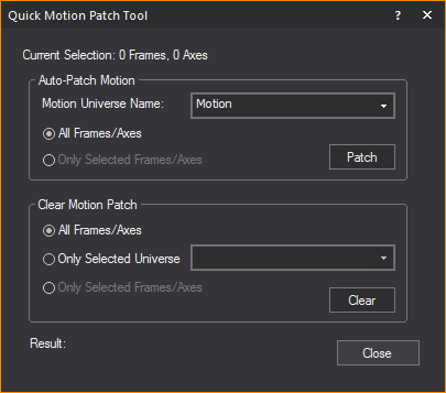
3In the Clear Motion Patch section, select either All Frames/Axes OR Only Selected Frames/Axes to be cleared the from the motion universe.
4Select Only Selected Universe radio to clear the selected frames/axes from only a specific motion universe. Select the specific universe from the drop-down list. Otherwise, the selected frames/axes will be cleared from all universes.
5Click Clear.
6The chosen frames/axes will be cleared from the selected motion universe. A summary of the frames'/axes' patching will be displayed at the bottom of the Quick Motion Patch Tool window.
Custom library items are made of one or more objects, including custom items that you have drawn, as well as existing library items. You can save a custom library item for a complex object that you have drawn and think you might want to use again.
When you save custom library items, all of the item’s original properties are saved, including its texture and color. In addition, if the item that you are saving is broken down into separate elements, then these elements are also saved with the item and can be viewed on the Appearance tab. For example, if you are saving an object like a riser, each of the four riser elements is saved with the custom library item.
Notes:
nYou cannot save fixtures or hanging structures, such as pipes and truss, as components of custom library items.
nYou cannot rename the elements of custom library items in the Appearance tab; therefore, it is recommended that you give elements custom names before you save the item as a custom object. For details, see “To rename object elements”.
nLibrary objects that are disallowed for Custom Library Item: you cannot use the following library objects to create custom library items.
n Axes
nFixtures
nCircles
nArcs
nPoints
nCameras
nFocus Positions
nFocus Lines
nFocus Arcs
nText
nRigging Points
nPipes
nTruss
nDimensions
nLinear Scales
nLED Walls
To create a custom library item
1Select the objects to be saved as a custom item.
2From the Library menu, choose Create New Library Item.
Tip: If the menu item is greyed out, one or more of the objects selected cannot be included in the custom library item.
3Pick a base point for the item. This will become the insertion point for the item.
Result: The Library Item Wizard appears displaying a rotating Shaded view of your new item.
4Type a name for the new library item.
5To make this item available to other documents, check the appropriate box.
6Click Next.
7Add or modify the path, if desired.
Note: The path is the location in the library where the item will be stored. An item assigned to the path “Custom/Tables” would be available in the custom section of the items library in a sub-category named Tables.
8Click Next.
9Type all pertinent information including manufacturer, weight, and any notes.
10Click Next.
11Type your name.
12Click Finish.
Result: The custom item is placed in the item library as per the path you specified in step 7.
Rules for deleting custom library items
In general, a custom library item that has been shared with the application library, (i.e. by selecting the Make this item available to other documents in the first step of its creation) can only be deleted from the Welcome Screen's Library Browser. A custom library item can be deleted from within a file as long as there are no instances of the item in the file.
The following are specific examples of when a custom library item can be deleted.
nA custom library item that was created in a file, and was added to the application library, cannot be deleted from the Library Browser while a file is open. The custom library object now exists in the application Library Browser. To remove the custom library item, it must be deleted from Welcome Screen’s Library Browser. This deletion cannot be undone.
Note: A custom library item will always be included in the “private library” of the file in which it was created. This means that if a custom library item is created (and used) in a file, then deleted from the application library, that item is still not removed from the file. Only once the item is removed from the application library, and the item is not in use in the file it was created in, may the item be deleted from the file. This deletion is permanent and cannot be undone.
nA custom library item that is created in a file, and is not added to the application library:
nCan be deleted from the Library Browser inside the file if no instances of the item are inserted into the file. The deletion cannot be undone.
nCannot be deleted from the Library Browser if there are instances of the custom item in the file.
nA "DWG" library item (imported from AutoCAD file and listed in the Library Browser) can be deleted while the file is open if no instances of the item are inserted into the file. The deletion cannot be undone.
To delete a custom library item
If you do not want to keep a custom library item any longer, you can delete it from the Library Browser.
1In the Library Browser, navigate to the folder where you stored the custom library item.
2Highlight the library item name, and then right-click and choose Delete.
Note: This option is disabled if the item is currently inserted in your plot. You must delete the item from your plot, and then save and close the file. When you reopen the file you can delete the item from the Library Browser.
3A message box appears telling you the action is irreversible. Click Yes to delete the item.
Use the Pipe and Drape Wizard to add lengths of drapery in your drawing. You can add default length and height of drapery, or specify custom sizes for your drapery panels, and define drapery properties such as color, texture, and material.
The several components in a drape line are shown in the graphic:

nDrape panels: These are the individual pieces of fabric that hang from the horizontal pieces of pipe called crossbars. You can specify the number of drape panels in each of the pipe and drape drawing methods. The default number of panels is three per section.
nSection: A section consists of a series of drape panels hanging from a horizontal pipe called a crossbar, which is supported on each end by an upright pipe. You can specify the number of panels per section and, based on the drawing method you choose, either the exact width of the section or the maximum width.
nUpright pipes: These are the pipes that stand on either end of each section in your drape line, supporting the crossbar pipes.
nBase plates: These are support plates for the upright pipes.
The Wizard offers you two drawing options:
nDraw: This option gives you the most flexibility when drawing your drape line. It enables you to specify the height, maximum width of a section, and the number of drape panels per section. When you click Finish, the Wizard returns you to the drawing where you can click and drag to draw as many drape lines as desired in whatever length required.
nSpecify: This option enables you to define the height, width, the number of sections in your drape line, and the number of drape panels per section. This option enables you to either draw a new drape line section, or add to an existing drape line.
To draw pipe and drape - Draw method
Note: If you are adding a new drape section to an existing panel in your drawing, click the Midpoints snap tool first. This ensures that the new drape panel “snaps” to the existing one in the correct position.
1From the Draw menu, choose Pipe and Drape Wizard.
Result: The Select Drawing Method window appears.

2Click the Draw option button, and then click Next.
Result: The Draw Pipe and Drape window appears.
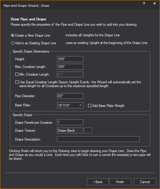
3Select Create a New Drape Line option to create a new section of the drape line; or select the Add to an Existing Drape Line option to add the next section of the drape line.
Notes:
nDrawing a new drape line includes all uprights for the drape line.
nAdding to an existing drape line uses an existing upright as the beginning of the added drape line.
4In the Height box, type the height of the drape line, or accept the default value of 15’0”.
5In the Max. Crossbar Length box, type the maximum length of each horizontal pipe, or accept the default value of 10’0”. This value sets the longest length of the horizontal pipe in a section between the upright pipes. If you click to insert a section at a shorter interval than this value, WYSIWYG automatically adjusts the width of each drapery panel accordingly and a shorter section is inserted in the drawing.
6Select the Min. Crossbar Length checkbox and type the minimum length of each horizontal pipe, or accept the default value of 1”. This value sets the shortest length of the horizontal pipe in a section between the upright pipes.
7Select the Use Equal Crossbar Length/Space Upright Evenly checkbox to automatically set the same length for all the crossbars. If you clear this checkbox, then WYSIWYG creates drapery panels of equal size for all full-size sections, but resizes the panels in the last section accordingly if you choose to make this panel smaller.
8In the Pipe Diameter box, type the diameter of all crossbars and upright pipes.
9From the Base Plate drop-down list, select the size of the base plate support for the upright pipes.
10Select the Add Base Plate Weight checkbox to add thickness to the base plate in Wireframe and Shaded views.
11In the Drape Panels per Crossbar box, type the number of drape panels that you want to see in each section of the drape line, or accept the default value of 1 panel per section.
12The default or previously set texture of the drape is displayed in the Drape Texture box. To change the texture, click the Drape Texture ellipsis button to browse and select a new texture from the Texture Select dialog box that opens.
13In the Drape Description box, type additional user information or identification for the drape line, which will be displayed in Reports.
14Click Finish.
15Click in the desired spot in your drawing where you want to start drawing the drape line.
16Move the cursor to the spot where you want the first section to end, and click. Then move your cursor to the spot where you want the next section to end, and click. You can draw as many sections as you like. When you are finished drawing your drape line, right-click and select Finish Pipe and Drape.
Note: For information on customizing the new drape line, see “To customize drapery elements (color, material, and texture)”.
To draw pipe and drape - Specify method
Note: If you are adding a new drape section to an existing panel in your drawing, click the Midpoints snap tool first. This ensures that the new drape panel “snaps” to the existing one in the correct position.
1From the Draw menu, choose Pipe and Drape Wizard.
Result: The Select Drawing Method window appears.

2Click the Specify option button, and then click Next.
Result: The Specify Pipe and Drape window appears.

3Select the Create a New Drape Line option to create a new section of the drape panel; or select the Add to an Existing Drape Line option to add the next section of the drape panel.
Notes:
nDrawing a new drape line includes all uprights for the drape line.
nAdding to an existing drape line uses an existing upright as the beginning of the added drape line.
4To specify the total length of the drape line section, select Total Length and type the length of the drape line, or accept the default value of 10’0”. The Crossbar Length option is disabled if the Total Length option is selected.
5To specify drape line section by the length and quantity of it’s crossbars, select Crossbar Length and type the length of the crossbar, or accept the default value of 10’0”. The Total Length option is disabled if the Crossbar Length option is selected.
6In the Number of Crossbars box, type the number of crossbars in the drape line, or accept the default value of 1.
Note: The length of each crossbar will automatically change with reference to the specified Total Length and Number of Crossbars.
7In the Height box, type the height of the drape line, or accept the default value of 15’0”.
8In the Pipe Diameter box, type the diameter of all crossbars and upright pipes.
9From the Base Plate drop-down list, select the size of the base plate support for the upright pipes.
10Select the Add Base Plate Weight checkbox to add thickness to the base plate in Wireframe and Shaded views.
11In the Drape Panels per Crossbar box, type the number of drape panels that you want to see in each section of the drape line, or accept the default value of 1 panel per section.
12The default or previously set texture of the drape is displayed in the Drape Texture box. To change the texture, click the Drape Texture ellipsis button to browse and select a new texture from the Texture Select dialog box that opens.
13In the Drape Description box, type additional user information or identification for the drape line, which will be displayed in Reports.
14Click Finish.
15Click in the desired spot in your drawing where you want to start drawing the drape line.
16Move the cursor to the spot where you want the first section to end, and click. Then move your cursor to the spot where you want the next section to end, and click. You can draw as many sections as you like. When you are finished drawing your drape line, right-click and select Finish Pipe and Drape.
Note: For information on customizing the new drape line, see “To customize drapery elements (color, material, and texture)”.
To quickly change pipe and drape wizard settings
This procedure shows you how to quickly change some of the structural pipe and drape settings for a selected drape line, such as the height and diameter of the upright pipes and crossbars. Use this procedure to customize the structural properties of a single drape line.
1In your drawing, select the pipe and drape sections that you want to customize.To select multiple sections, press CTRL, and then click the appropriate sections.
Note: The sections that you select must have been drawn in the same way. For example, all drape lines created with Specify method.
2Right-click and select Change Pipe and Drape Settings.
Result: The appropriate Settings window appears. Based on the type of drape line that you selected, a different window appears.
3Change any of the settings that you see in this window. For help on any of the boxes, click in the box, and then press F1.
4Click Finish to save and apply your new settings.
To customize drapery elements (color, material, and texture)
You can add custom color, texture and material to selected drapery elements (such as the front and back of the drape panels, the crossbars, upright pipes, the drape loops that attach to the crossbars, or the drape lines as a whole).
Notes:
nIf you select multiple drape lines in your drawing, you can apply the same properties to all of them simultaneously through the following procedure. However, note that if you had already selected varying properties (for example, if you had chosen one color for the front panel of some drape lines, but another color for the front panel of others), or if some of the elements had no properties selected at all, then when you choose new properties in the following procedure, it applies to all drape lines selected, overwriting any existing settings that you may have saved.
nWhen you select multiple drape lines, the Appearance tab only lists the properties of selected elements if they are common across all drape lines. For example, if the front panel of all selected drape lines already has the same custom texture applied, and it is set to tile in one meter squared intervals, then these values are shown in the Appearance tab. However, if at least one of the front panels in the selected drape lines has a different custom texture value applied, the Appearance tab does not list the texture settings at all. If you choose new texture settings, your choice overwrites all existing settings for the selected element across all selected drape lines.
nYou can apply the same properties to all drapery elements by highlighting “Group” in the Elements box.
1In your drawing, select the pipe and drape sections that you want to customize. To select multiple sections, press CTRL, and then click the appropriate sections.
2With the desired sections selected, right-click and select Properties.
Result: The Properties window appears.
3Click the Appearance tab.
4In the left pane, click the drapery element that you want to customize. For example, to customize the front of the drape panels (each panel is double-sided), click Drape Front.
Note: You can select multiple elements by pressing CTRL, and then clicking the elements; you can select all elements by clicking Select All.
5You have a choice of applying one of the following settings to the selected elements:
nLayer Rendering Color: Select this option to apply the same color as the current layer to the selected elements.
nCustom Color: Select this option and click the color box to apply a custom color. In the resulting color dialog box, select the custom color that you want to use, or click Define Custom Colors to create your own color.
nTexture from Library: Select this option to apply a custom texture file from the WYSIWYG library to the selected elements, and then click the ellipsis button (...). In the resulting dialog box, navigate to and choose the desired texture.
nImage Source: Select this option to apply a custom texture file that you have created and saved in either .bmp, .jpeg, .png, or .gif format. For information on image sources, see “To create a new image source in the Image Manager”.
nVideo Source: Select this option to apply a video source or a subsource as a “dynamic texture”. Choose a previously created video source or subsource, or create a new video source or subsource. For information on video sources, see “Video Manager”.
nUse Normal Map: Select this option to apply an Image Source that is a Normal Map, to create the perception of fragmented surface texture detail and depth, making objects look more realistic.
Select from the drop-down list an existing Normal Map image or click New to create a new Normal Map image via the Image Manager.
Note: This drop-down lists all Image Sources that appear in the Image Manager; as such, Image Sources which are Normal Maps should be named appropriately for easy identification.
nScale: Select the height or depth of visual effect created by the Normal Map. Select from the drop-down list, the percentage scale value from not visible (0%) to maximum value stored in the imported Normal texture/image (100%).
6If you have chosen to apply a texture to the elements, you can choose how the texture will appear on the selected drapery elements as follows (if you have applied a color instead, you can skip directly to step 7):
nTo view the texture file as a series of square or rectangular “tiles” that are repeated over the entire surface of the drapery element, click the Tile option button, and then type the size of the tiles in the boxes provided.
nTo view the texture file stretched out as a single surface over the entire drapery element, click the Stretch option button.
nTo preserve the aspect ratio of the texture so it is not distorted when stretched over the element, click Keep Aspect Ratio.
nTo choose a custom border color for the texture when it is stretched over the surface of the element, click the Border Color box, and then choose the custom color.
nIf you have selected Use Normal Map, specify the number of times the Normal Map is multiplied across the object (element) to which it is applied. Type the value in the Normal Map Size Multiplier box. (Enter a valid number between 0.01 and 100.)
Notes:
nThe default value of 1 results in no changes to the Normal Map’s size; values lower than 1 will increase the size of the Normal visual effect, and values higher than 1 will decrease it.
nThe Normal Map Size Multiplier operates within the Tile or Stretch Texture Options.
nTo set the angle at which the texture appears on the drapery element, type or select the value in degrees from the Rotation (Deg.) drop-down list.
nTo change the color of the texture, click the Color Tint color box and select a new color, then click the Scale drop-down list box to specify the intensity of the color.
7To choose a custom material for the selected drapery elements (such as metal, paper, plastic, or fabric) click the ellipsis button (...) in the Material Properties section.
8In the resulting dialog box, navigate to and highlight the desired material, and then click Select.
9Click Apply.
10You can apply a transparency level to the selected element. Based on the settings that you have chosen for color, texture, and material, the transparency options vary as follows:
nTransparency: This setting controls the proportion of light that passes through the material. All materials in WYSIWYG specify a level of transparency that varies from one material to the next. For example, glass is more transparent than brick. If you select Default, the transparency level is set to 0% (opaque).
nSpecular Level: This setting controls how prominent other specular effects appear on the material.
nSpecular Gloss: This setting controls the level of gloss the material will project.
nSpecular Color Source: This setting controls the amount of light that is projected on the material.
nLight Reflection: This setting controls the amount of light that is reflected off the material.
Notes:
nFrom the drop-down lists, change any of the material properties. Use the Reset button to revert back to defaults.
nThe beam will pass through a surface with the Transparency value set to 80% or greater. The beam will not pass through the surface when the value is lower than 80%.
11Select Display Reflection in Shaded Views checkbox to display the set reflective characteristics in Shaded Views.
12Click Apply.
13Click OK to save your changes and close the Properties dialog box.
To customize pipe and drape structure for individual drape lines
This procedure shows how to the structural properties of individual drape lines that you have selected.
Note: While the tabs in the Properties window are best used to customize a single drape line, if you have selected multiple drape lines, the values that you type in these tabs apply to all selected drape lines; they overwrite any custom settings that you may have previously saved for individual crossbars, uprights, or drape panels.
1In your drawing, select the pipe and drape section that you want to customize.
2With the desired section selected, right-click and select Properties.
Result: The Properties window appears.
3On the Properties window, click the Pipe and Drape tab.
Pipe: This section displays the properties of the drape line crossbars and upright pipes.
nCrossbar section:
nLength: Type the length of all crossbar pipes in the selected drape line.
nDiameter: Type the diameter of all crossbar pipes in the selected drape line. Updating the crossbar diameter will update the loop diameter.
Upright
nHeight: Type the height of all upright pipes in the selected drape line. Changing the upright height will update the height of the drape line.
nDiameter: Type the diameter of all upright pipes in the selected drape line.
nBase Plate: Select from the Base Plate drop-down list, to change the size of the base plate support for the upright pipes.
nSelect the Add Base Plate Weight checkbox to add thickness to the base plate in Wireframe and Shaded views.
nUse Document Defaults (Segments): Click to clear this checkbox if you want to specify the number of segments that comprise the circumference of the crossbar pipes. You can choose between three and 40 segments. This value is largely for rendering purposes—the greater the number of segments, the greater the rendering time. Leave this checkbox checked to accept the default value of 8 segments.
Drape: This section displays the properties of the drape line panels.
nPanel section:
nDescription: Type to add or replace the additional information for the drape line.
nHeight: Type the height of all panels in the selected drape line.
nWidth: Type the width of all panels in the selected drape line.
nLoop Diameter: Type the diameter of the loops that wrap around the crossbar pipes at the top of all panels in the selected drape line. This value should be greater than the diameter of the crossbar pipes.
nUse Document Defaults (Segments): Click to clear this checkbox if you want to specify the number of segments that comprise the drape panel loop that wraps around the crossbar pipe. You can choose between three and 40 segments. This value is largely for rendering purposes—the greater the number of segments, the greater the rendering time. Leave this checkbox checked to accept the default value of 8 segments.
nNotes: Type additional user information for the drape line.
nCurtain
nEnable: Select this checkbox to display the curtain as a wave in Plan View.
nCurtain Folds (2D Plan Only)
nStyle: Choose the style of how the wave is displayed.
nDepth: Type the depth of each wave period.
nWidth: Type the width of each wave period.
nNumber of Segments: Type the number of segments for the 2D wave object.
4Click Apply.
5Click OK.
Result: Your changes are applied to all selected drape lines.
There are three types of Zones which can be defined: Rectangular Zones, Cylindrical Zones and Spherical Zones. These new CAD objects are used to define zones of interest for the BlackTrax system, which can be associated with a trigger relationship in the BlackTrax software.
The BlackTrax Zone objects must be given a unique name when created so they can be referenced in the BlackTrax System. By default, BlackTrax Zones will appear as a red, semi-transparent volume in the Shaded views.


 Plan View
 Left View
 Right View
 Front View
 Back View
 Isometric View
 Workplane Plan
 Truss Assembly snap
 Pipe snap
  Focus snap
  Gel (color)
 Lamps
Lamps


