All of the WYSIWYG levels use the same set of screens. The user interface was designed to facilitate smooth transitions from mode to mode, and to keep the data organized and easy to find.
In this section
When you start WYSIWYG, the Welcome window appears. The application level is shown in the upper right corner of the window.
On the Welcome window or from the File menu, you can choose to create a new File or a new Project; or open an existing file or project. A list of template files and a list of recently saved files are displayed on the screen.
On the Welcome window, click a file name to start working with WYSIWYG.
Note: You can open an existing WYSIWYG file by dragging the file icon from the desktop or folder and dropping it into the Welcome window.
To open an existing WYSIWYG file using drag and drop
1Open the WYSIWYG Welcome window.
Select the “.wyg” file where it is located.
2Drag and drop the file icon into the Welcome window.
Result: The selected “.wyg” file will open.
When saving your work as a WYSIWYG Project, the “.wyg” file and all its associated files are stored in a folder structure automatically within the My Projects folder. If you choose to accept the default settings when a WYSIWYG Project is saved, all files associated with that project are automatically stored in the Project folder and its subfolders. (e.g. C:\Users\<UserName>\Documents\WYSIWYG Files\My Projects\...)
A WYSIWYG Project can be packaged as a zip file with the option to include the external images and videos used in the file.
When you start working on a file, use the Mode buttons located along the top of the user interface to access the different working modes available within the WYSIWYG levels. The currently selected mode is shown in orange, while modes not selected are shown in grey. Clicking the appropriate button will change the view to that mode.
Note: Specific mode tabs can be selected from the mode’s drop-down menu, enabling rapid change of views easily.

CAD mode is where you create your show drawings or “model.” This includes drawing your venue, set pieces, lighting positions, focus positions, and lighting fixtures. This is also where you can import CAD files. CAD mode operates like many other CAD programs, so many of the concepts will be familiar to those who have used a computer-aided drafting program before. WYSIWYG adds features that are specific to the entertainment industry, such as a comprehensive 3D library containing truss, lighting equipment and accessories, as well as props, musical instruments, and various human figures.
As you draw in CAD mode, all your fixture information is compiled into spreadsheets and accessed in Data mode. In this mode, you can view and edit the data for all your fixtures. Data mode operates like many other spreadsheet programs, so many of the concepts will be familiar to those who have used a spreadsheet program. The CAD and Data modes are interactive, where modified information from either modes gets updated in the other.
Design mode provides an avenue for experimentation for lighting designers. Design mode can be a troubleshooting tool or a creative tool to help you come up with cue concepts. In Design mode, you can create static lighting looks using the design tools, and then save and render those looks to output photo-realistic pictures. You can turn on and control fixtures without having to patch or connect to a console.
Presentation (PRES) mode contains all the tools necessary for creating professional printouts of your show document including reports, plots, and images. As with all other modes, the contents of the Pres mode are continually updated as you draw, input data, and modify your show file. In addition to being able to create your plots, WYSIWYG provides a series of default plots and reports that are ready for printout. These defaults can be used as is or customized to your preferences.
Live mode is where you can graphically simulate the output of a lighting control console or compatible offline editor. This is where you can pre-cue and visualize your show. In Live mode, you can render to create photo-realistic pictures of the simulated lighting looks. Live mode will fully display a console's output, including transitions from cue to cue, allowing you to see the programmed changes to lights over time.
The following working modes are available in WYSIWYG Report:
nCAD
nDATA
nPRES
The following working modes are available in WYSIWYG Design:
nCAD
nDATA
nDESIGN
nPRES
The following working modes are available in WYSIWYG Perform:
nCAD
nDATA
nDESIGN
nPRES
nLIVE
Beneath the work area in each mode is a series of layout tabs. A layout is a configuration of work views. Views and layouts are mode specific.
You can create custom layouts in CAD, DESIGN, and LIVE modes. Quad layouts are the only editable layouts, but you can only change the sizes of the panes. For more information, see “Custom tab window layout”.
WYSIWYG supports pop-up frames and has multi-monitor functionality, thus providing alternative tools for customizing your work environment. These features are discussed below.
Click the appropriate Layout tab to change layouts.
Views are the windows in the work space. The windows are pre-configured on the screen based on the layout, as discussed above.
The WYSIWYG views include: Wireframe, Flight Case, Shaded, Spreadsheet, Patch, Error, Report, Image, Plot, and Worksheet.
The layouts and views available in each mode are discussed at the beginning of each chapter.
For more information, see “Wireframe views” and “Shaded views”.
You can place a view in a “pop-up frame” so that it remains active across modes. For example, if you place the patch view in a pop-up frame, it will remain visible even if the mode is changed from DATA to CAD.
The position of pop-up frames are remembered when a file is saved. When the saved file is reopened, all pop-up frame positions will be remembered and set exactly how they were working last.
To place a view in a pop-up frame
1Make the desired window active.
2Click the Pop-Up Window tool on the View toolbar.
|
|
The Pop-Up Window button. |
Result: A new window containing a copy of the selected view opens.
nPop-up frames retain all the functionality of the original view so you can work in the pop-up view if you want to.
nAre fully integrated with the remaining show document and are continually updated (and vice versa).
nCan be resized and moved to any location on the screen or across monitors.
To display pop-up frames in full screen mode
1Make the pop-up window active.
2Click the Full Screen button.
|
|
The Full Screen button. |
Result: The pop-up frame expands to fill the entire screen with no title bar visible.
Tip: To return the pop-up frame to normal size, press ESC.
To minimize a pop-up frame
1Double-click the title bar of the pop-up window.
Result: The title bar only is displayed.
Tip: You can also click the Minimize button.
|
|
The Minimize button. |
You can create custom tab layouts and specify your workspace. WYSIWYG provides this feature in the CAD, DESIGN, and LIVE modes, and you can customize your workspace with any combination of layout windows, and then save these settings in a layout tab.
Your custom tab is stored and always available in your computer except when deleted.
The Views that will display in a Custom tab are:
nCAD or DESIGN or LIVE Wireframe view
nCAD or DESIGN or LIVE Shaded view
nDATA Spreadsheet view
nDATA Patch view
Note: You can create up to 10 custom tabs in your installation.
To create a custom tab
1In CAD or DESIGN or LIVE mode, from the View menu, choose Custom Tab > Create.
Note: You can also click the + tab by the layout tabs.

2The New Custom Tab window appears.
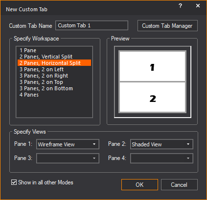
3In the New Custom Tab window, in the Custom Tab Name field, enter a name for the new tab.
4In the Specify Workspace section, select how many panes will be in the custom tab.
Note: A preview of how the tab will look appears in the Preview section.
5In the Specify Views section, select what view will be displayed inside each pane from the drop-down list.
Note: Refer to the Preview section for the location of the pane in the custom tab.
6Select the Show in all other Modes checkbox to make the custom tab and custom workspace available in CAD, DESIGN, and LIVE modes.
7When done customizing the tab, click OK.
Result: The custom tab is created. The custom tab will appear with the default tabs at the bottom of the layout.
nCustom tab in CAD mode:

nCustom tab in DESIGN mode:

nCustom tab in LIVE mode:

To rename a custom tab
1In CAD or DESIGN or LIVE mode, select the custom tab you want to rename.
2From the View menu of the selected mode, choose Custom Tab > Rename.
Note: You can also right-click the custom tab and select Rename.
3The Enter new tab name dialog appears.

4In the Enter new tab name dialog box, type the new name for the custom tab.
5Click OK.
Result: The custom tab is renamed.
To duplicate a tab
You can copy any existing tab in CAD, DESIGN, and LIVE modes. This will create an exact duplicate of the original tab. You can then use or edit both tabs as needed.
1In CAD or DESIGN or LIVE mode, select the custom tab you want to copy.
2From the View menu of the selected mode, choose Custom Tab > Duplicate.
Note: You can also right-click the tab and select Duplicate.
Result: The selected tab is copied and appears with the other tab.
To hide a tab
You can hide a tab that you do not want to see in a mode. This is useful if you have a number of custom tabs and want to reduce clutter.
1In CAD or DESIGN or LIVE mode, select the custom tab you want to hide.
2From the View menu of the selected mode, choose Custom Tab > Hide.
Note: You can also right-click the tab and select Hide.
3The selected tab will be hidden from view.
To unhide a tab
1In CAD or DESIGN or LIVE mode, from the View menu, choose Custom Tab > Unhide > [Hidden tab name].
Tip:
nTo unhide all hidden tabs, select Open all Hidden Tab.
nYou can also right-click the tab and select Unhide > [Hidden tab name].
Result: The selected hidden tab is visible again.
To delete a tab
1In CAD or DESIGN or LIVE mode, select the custom tab you want to delete.
2From the View menu of the selected mode, choose Custom Tab > Delete.
Result: A dialog box appears asking if you really want to delete the tab.
3To confirm the deletion, click YES.
Result: The tab is permanently deleted.
To change tab ordering
You can change the order which tabs are ordered.
1In CAD or DESIGN or LIVE mode, select the custom tab you want to move.
2Click and drag the tab left or right to a new position.
The Custom Tab Manager is a feature to help you keep track and manage any custom tabs you create.
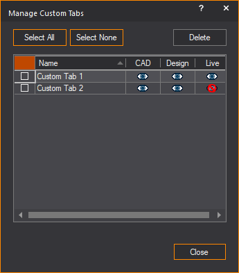
nSelect All: Will select all custom tabs in the manager.
nSelect None: Will clear all custom tabs in the manager.
nDelete: Will delete the currently selected custom tab(s).
nName: The name of the custom tab.
nCAD: Click the icon in this column to display or hide the custom tab in CAD mode.
nDesign: Click the icon in this column to display or hide the custom tab in Design mode.
nLive: Click the icon in this column to display or hide the custom tab in LIVE mode.
To access the custom tab manager
In CAD or DESIGN or LIVE mode, from the View menu, choose Custom Tab > Custom Tab Manager.
Note: The Manage Custom Tabs window appears.
From the Options menu in the Welcome window, you can choose a different language that will be used in WYSIWYG. Selecting a different language will require to restart WYSIWYG. English, français (French) and italiano (Italian) are the options available at the present, and more languages will be added in the future.
To open WYSIWYG with a different language
1On the Welcome window, click Options > Language and choose either English or français or italiano.
Result: If the selected language is different from the default, the “Your changes will not be applied until the next time WYSIWYG is started. Please remember to save your work.” dialog box appears.
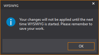
2On the dialog box, click OK.
3Exit WYSIWYG.
4Start WYSIWYG again.
Result: WYSIWYG opens with the selected language.
You can save WYSIWYG settings that are specific to a particular installation of the WYSIWYG software into an external file with a “.wud” extension. You can then load this file into WYSIWYG to automatically load all the user settings saved in the “.wud” file. With “.wud” files, you can share your custom user data between multiple computers and when upgrading to newer WYSIWYG releases.
The following user data and settings are found in a.wud file:
nModified Fixture Symbols/Attribute Layouts
nCustom Conventional Fixtures
nCustom Gobos
nCustom Library Items
nFixture Associations (DWG/SKP/MVR)
nToolbar Positions & Application Appearance Options
nLayout Templates
nShared Keys
nFixture Attribute Layout Templates
nCustom Layout tabs
nTruss Manager Data
Attention: WYSIWYG User Data files can only be imported and exported from the WYSIWYG Welcome window.
To export a user data profile
1On the Welcome screen, click File > Export User Data.
Result: The Export User Data window appears.
2In the Export User Data window, select the checkbox(es) of features you want to export. Select the checkbox on the top row of the list to select all the check boxes below.
3Click Continue.
4The Save As window appears.
5In the Save As window, navigate to where you want the file to be saved, and enter an appropriate name in the File Name field.
6Click Save.
Result: The User Data Profile is saved at the chosen location.
To import a user data profile
1On the Welcome screen, click File > Import User Data.
Result: The Select User Data File window appears.
2In the Select User Data File window, navigate to where the desired WYSIWYG User Data file (*.wud) is located. Select the file and click Open.
Result: The Import User Data window appears.
3In the Import User Data window, select the checkbox(es) of features you want to import. Select the checkbox on the top row of the list to select all the check boxes below.
Note: [Overwrite] appears next to settings stored in the *.wud file that will overwrite existing WYSIWYG settings if imported.
4Click Continue.
Result: The User Data settings are imported successfully. WYSIWYG will need to restart for the new settings to take effect.
Exporting and resetting WYSIWYG UI
You can save your user interface settings into an external file with a “.wud” extension, which can be loaded back into WYSIWYG. Click Export my WYSIWYG Registry on the WYSIWYG Tech Support dialog box that appears when you click Support from the Help menu.
You can reset the user interface settings of WYSIWYG to default by clicking the Reset my UI to default button on the WYSIWYG Tech Support dialog box that appears when you click Support from the Help menu.
Shortcuts are created for quick access to library items and view types, among other things. The shortcut bars are located on the left side of your screen. Shortcut bars are mode and layout specific. Each layout has designated shortcut bars.

In general, there are three types of shortcuts:
nNavigation
nLibrary
nViews/Tools
The first type of shortcut is used for navigation purposes. The navigation shortcuts are:
n Navigation
n Views
Views
Navigation shortcuts store the mode and layout destination. For example, you can save a navigation shortcut to DATA mode / Patch layout. The next time you want to go back to that location, click the shortcut to save you at least one step.
View shortcuts store the plot type and zoom level. View shortcuts only apply to Wireframe views.
The second type of shortcut is used in place of browsing the library. The library shortcuts are:

The final type of shortcut is used to open and save views and tools. The views/tools shortcuts are:

The procedure for creating, modifying, and working with shortcuts is the same regardless of the type of shortcut.
1Right-click on the open space on the appropriate shortcut bar, and then click the appropriate New option.
Note: For navigation type shortcuts, ensure that the destination is set up, and then proceed with step 1.
2Based on the type of shortcut, select the object or type a name for the new shortcut on the dialog box that appears.
3Click Insert or OK.
Result: The shortcut is created and added to the bottom of the list on the shortcut bar that you selected in step 1.
To remove a shortcut
1Right-click the shortcut icon that you want to remove.
2Click Delete.
Result: You are prompted to confirm the deletion.
3Click OK to confirm.
Result: The selected shortcut is deleted.
To rename a shortcut
1Right-click the shortcut icon that you want to rename.
2Click Rename.
3Type a new name for the shortcut.
4Click OK.
Result: The selected shortcut is renamed.
1Right-click the shortcut icon that you want to clone.
2Click Clone Shortcut.
3Type a name for the copy.
Result: The selected shortcut is cloned and the copy is added to the bottom of the list.
You can arrange shortcuts on the shortcut bar area by using drag-and-drop functionality.
1Click the shortcut that you want to move.
2While holding down the mouse button, use ALT to move the shortcut to the desired location.
3Release the mouse button to place the shortcut.
To set the display size for shortcuts
Right-click on the open space on the appropriate shortcut bar, and then click either Icons or List (depending on your current setup).
Result: When you choose Icons, all shortcuts are displayed as icons. List will cause the shortcuts to be listed in the shortcut bar area, thereby allowing you to fit more shortcuts in the area.
The settings are retained for all shortcuts.
Note: To scroll to the bottom of a long list of shortcuts, use either the scroll button on your mouse or the scroll bar along the side of the shortcut bar.
To use a shortcut
Click the shortcut icon.
Note: As with all objects in WYSIWYG, all shortcuts have properties that affect the object being inserted, the view or tool, or the navigation method.
To modify a shortcut’s properties
1Right-click the shortcut icon that you want to modify.
2Click Properties.
Result: The Properties dialog box appears. The settings modified here affect the object, view, tool, or navigation destination of the selected shortcut. An example of the Navigation Shortcut Properties dialog box is shown below; however, the shortcut properties window varies based on the type of shortcut that you select.
3In the Name box, type the new name of the shortcut.
4To open the shortcut in a popup frame, select the PopUp Windows checkbox. For more information on pop-up frames, see “Pop-up frames”.
You can configure the shortcut bar to show fewer/more categories, and reorder the categories that you see.
1On the bottom right corner of the shortcut bar, click the Configure Shortcuts arrow.
2In the resulting pop-up menu, you have the following choices:
nShow More Buttons: Click to add the next shortcut category to the bottom of the shortcut bar. This button is enabled only if you have hidden some shortcut categories.
nShow Fewer Buttons: Click to remove the bottom-most shortcut category from the shortcut bar. Click consecutively to remove each category shown from the bottom upwards.
nNavigation Pane Options: Click to arrange the order of the shortcut categories shown on the shortcut bar.
Shortcuts in your file can be sorted and deleted as needed. Sorted shortcuts can be managed manually or alphabetically. You can also insert separators between shortcuts to group, segregate and organize the shortcut icons.
1On the shortcut bar, right-click and choose Manage Shortcuts menu.
Result: The Manage (shortcut type) Shortcuts window appears.
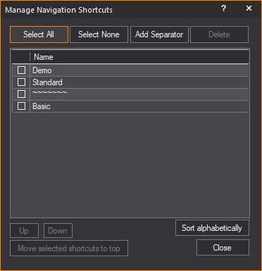
2In the Manage (shortcut type) Shortcuts window, select the checkbox next to the shortcuts you want to manage. You may click Select All to select all shortcuts in the list.
3To insert a shortcut separator in the list, select a shortcut and click the Add Separator button. A separator indicator will be added to the list after the selected shortcut.
Result: On the shortcut bar, a shortcut separator appears on the space below the selected shortcut.
Tip: On the shortcut bar, you may also right-click on the space where you want to insert a separator and click the Add Separator menu.
4To move a selected shortcut in the list, click Up or Down. The shortcut will move one position up or down respectively.
5To move a selected shortcut to the top of the list, click Move selected shortcuts to top.
6To sort selected shortcuts alphabetically, click Sort alphabetically.
7To remove a selected shortcut, click Delete.
The Menu bar is located within the WYSIWYG user interface, below the Mode buttons and above the work area. The available menus change when moving from mode to mode. The individual menus are explained within the context of each mode chapter.
The Menu bar is dockable. It has a grab bar on the left that is used to move the Menu bar around the screen. It may be placed on the edges of the work area; top, bottom, left, or right. It may also be dragged off the edge of the work area and into its own window. This window remains on top of the WYSIWYG screen and can be dragged anywhere on your display.
Menu commands can be accessed using a mouse, keyboard, or by using hotkeys.
To access menu commands using the keyboard
1Use ALT + n, where n is the underlined letter in the menu name.
Result: The menu is displayed.
2Use the key corresponding to the underlined letter in the command that you want to execute.
Note: Some commands have shortcuts that do not require menu selection. In those cases, the shortcut keys are listed to the right of the command in the menu.
Example: To undo the last command, use CTRL + Z.
Toolbars provide button access to most commands. This is in lieu of selecting the commands through the menus in the Menu bar.
Toolbars, like menus, are mode sensitive. However, unlike menus, you can customize how the toolbars are displayed and which toolbars are open for each mode. Toolbars that are greyed out in the toolbar selection list are not used in the current mode.
Toolbars are typically found directly under the Menu bar and have a grab bar on the left that is used to move the toolbar around the screen. They can be placed on the edges of the work area (top, bottom, left or right), and can also be dragged off the edge of the work area and into their own window. This window remains on top of the WYSIWYG screen and can be dragged anywhere on your display.

To save on space, similar toolbar buttons are grouped together in a Toolbar drop-down menu. If a drop-down menu is available for a button, it can be identified by the small triangle in the lower right side of the button.
Click and hold the button until the drop-down menu appears, and then click on your choice. The selected item in the drop-down menu is then displayed at the top level of the toolbar.
The following toolbars are available (listed in alphabetical order).
Align toolbar (CAD, PRES/Layouts and /New Plots)


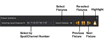
Fixture Selection toolbar


Layout Text (Pres) toolbar (Pres > Reports, Layouts and Worksheets)
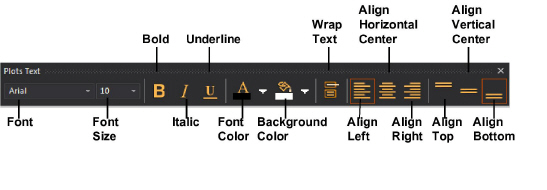


Text toolbar (CAD, and PRES > New Plots)


To hide and display toolbars using the toolbar list
1Right-click on the toolbar area.
Result: The toolbar list is displayed.
2Click on the name of the toolbar that you wish to display. A check mark to the left of the toolbar name indicates it is currently displayed.
3Repeat to display or hide multiple toolbars.
Tip: From the toolbar list, choose Toolbars to open the Application Options dialog box. In this dialog box, you can choose multiple toolbars and configure other screen options, such as the Status bar and tooltips.
To hide and display toolbars using the options menu
1From the Options menu, choose Application Options.
2Click the Toolbars tab.
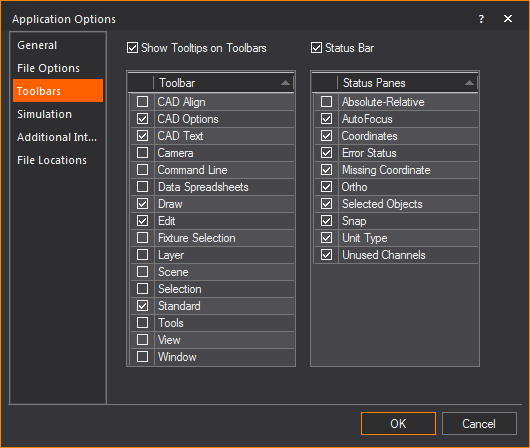
3Select the checkboxes of the toolbars that you want to display.
Note: Since toolbars are mode-sensitive, certain toolbars are disabled based on the mode that you are currently in.
Most tools in WYSIWYG create a separate window where all the options of the tool are available. Window positions of these tools can be customized to suit most work styles. If a WYSIWYG document is saved, WYSIWYG will remember the window preference of the tool the next time the document is opened.
Window position options can be accessed by clicking the down arrow at the top of the window, and opening the Window Position drop-down menu.

nFloating: The window will appear in the foreground of the WYSIWYG file. The window will not be attached to any border of the work space or any other window. If the resolution of WYSIWYG or the work space is resized, the window will remain in its current position and in the foreground.
nDocking: The window will be attached to a border of the work space. If the resolution of WYSIWYG or the work space is resized, the window will change its resolution to match the new work space size.
nTabbed Document: Tools with similar display options can share the same window space. The tabbed document can be either floating or docked. At the bottom of the window will be tabs showing the names of the different tools. Click on the tabs to switch between tools as needed.
nAuto Hide: This option is only available for docked windows. When enabled, the window will be hidden from view by default. A tab will appear on the side of the WYSIWYG application window with the name of the auto hidden window. When the tab is selected, the window will reappear in its previously docked location. The window will continue to be visible until another window or feature is selected, or until you click off of it.

nHide: The selected window will close. To view the window again, the feature must be accessed again.
To display a window as tabbed
1Identify the tools/features that you wish to tab together.
2Click and drag one tool window over to another tool window, until the arrows appear over the tool.
3Without releasing the mouse, move your cursor to the square in the middle of the arrows that appear, and then release the mouse.
Result: The tools are now tabbed together.
To toggle the auto hide setting of a window
Click the Pin icon to toggle the Auto Hide setting of a window.
Floating Toolbars are available in WYSIWYG to offer common features conveniently at your cursor. When you right-click on a view, in addition to the usual right-click menu, a floating toolbar will appear either above or below the right-click menu (depending on where you clicked on the screen).
The icons displayed are the same as the ones displayed in the menus and toolbars. If you are not familiar with an icon, hover over it and a tooltip will appear displaying the feature's name.
The Status bar is displayed along the bottom of the WYSIWYG screen, below the Layout tabs. The Status bar displays the prompt line, the number of unused channels (WYSIWYG Perform), selected object information, and tracks the status of the snap, ortho and absolute coordinates commands. It also tracks and displays the coordinates of the cursor.

The Status bar can be turned on or off from the toolbar list. You can also customize the contents of the Status bar from the Application Options window.
For more information on setting the options of your drawing, see “Application Options”.
The prompt line displays the current status of a command within your drawing. If you are currently working with a command that requires multiple steps (the placement of a pipe, for example), the prompt line displays a message indicating the next step required to accomplish that task. The prompt line also displays a short description of a command when you point to it using your mouse.
In this display, “O” stands for the number of objects currently selected. The “F” stands for the number of fixtures selected and the “C” stands for the number of circuits currently selected.

Although there is never a limitation on how many fixtures can be patched in a file, there is a limitation on the number of DMX channels that can be simulated in LIVE mode. WYSIWYG will not simulate the DMX values being received on channels exceeding the Perform or Perform Lite channel counts of your system.
WYSIWYG Perform can visualize up to 131,072 DMX channels, the equivalent of 256 full DMX universes.
WYSIWYG Perform Lite can visualize/simulate up to 10,240 DMX channels, the equivalent of 20 full DMX universes.
The number of unused channels will appear on the Status bar in CAD, DATA, DESIGN, and LIVE modes.
Absolute and relative coordinates
This setting determines how coordinate information is displayed mid-command. In ABS (Absolute) mode, which is the default, the coordinates display always shows the coordinates currently under your cursor. In REL (Relative) mode, the Coordinates display shows the relative distance and angle from the last position, indicated with a mouse click.
Coordinates are displayed in the order of X, Y and Z. The coordinates display the position of the cursor as a distance from the origin of the drawing. For more information on coordinates and setting the origin point, see “Coordinate system and origin”.
Double-click this label to set the missing coordinate. The missing coordinate (X,Y,or Z) is the coordinate whose value cannot be entered by clicking on the screen. The easiest way to determine the missing coordinate in a Wireframe view is to move the mouse around and look at the Status bar at the bottom of the working area. You will see only two values changing. The value that is not changing is the missing coordinate for that view or workplane.
The missing coordinate is dependent on the plot type and the workplane selected. Once entered this value will affect all subsequent objects inserted in the current view. For example, if the missing coordinate is set to 5’ in a plan view, all objects will be placed 5’ off the floor (X,Y,5) until the missing coordinate is changed again. Note that the missing coordinate is not a move tool; objects are not moved to the missing coordinate value. The missing coordinate only affects subsequent inserts.
Click this label to toggle between metric and imperial units of measurement.
The snap and ortho entry shows the status of these items. If the indicator is white, a snap or ortho setting is active. If the indicator is dark grey, snap and ortho are not active.
The Instruction Tooltip is a helpful window that appears automatically when you start an operation. The Instruction Tooltip explains how to perform the current operation. The information shown is the same information that is displayed in the Status bar.
Note: By default the Instruction Tooltip is turned on.

For some operations, such as snapping truss or hanging a fixture, the tooltip color will be red when the operation can not be performed, then change to green when you can insert the object.

To turn off instruction tooltips
1From the Options menu, choose Application Option....
2In the General tab, clear the Enable Instruction Tooltip checkbox.
When you first create a new show document and enter CAD mode, WYSIWYG defaults to the Wireframe view. All drawing is done in Wireframe view. Click the Quad tab to display three Wireframe views and a Shaded view of your drawing.
To modify the point of view
nThe arrow keys move you in their respective directions.
nThe PAGE UP and PAGE DOWN keys zoom you in and out. You can also roll the middle mouse button up and down to zoom in and out. The zoom action is centered on the mouse pointer rather than the center of the window.
nIn a 3D perspective view (isometric or shaded), the CTRL key, in combination with any of the aforementioned keys, rotates you around your drawing.
nHolding down the middle mouse button will allow you to drag the drawing around the window. Alternatively, the Pan tool on the View toolbar also enables this type of movement.
|
|
The Pan button. |
nAt any time you can use the SHIFT key in combination with any of the movement keys to move in smaller increments.
nIn Shaded view, the mouse can substitute all key strokes. Click and drag to pan around and use the mouse wheel for zooming.
Zoom tools allow you to view smaller or larger sections of a plot or drawing. There are seven zoom tools available in WYSIWYG.
Note: The zoom tools are not applicable in the Shaded view; to zoom in or out in this view, use the arrow keys or the roller wheel on your mouse instead.
To access the zoom tools
1From the Zoom menu, choose one of the Zoom tools.
Tip: You may also use the Zoom tools on the View toolbar.
Result: The viewpoint is adjusted accordingly.
The Zoom tools that are available are listed in the following table.
|
Zoom tool |
Icon |
Description |
|---|---|---|
|
Zoom In |

|
Moves your viewpoint closer to the center of the view. |
|
Zoom Out |

|
Moves your viewpoint farther away from the center of the view. |
|
Zoom Fit |

|
Adjusts the viewpoint so that the extremities of the drawing fit into the current view. |
|
Zoom Fit All (only available on the Zoom menu) |
|
For Quad layout, adjusts the viewpoint so that the extremities of the drawing fit into the three Wireframe views simultaneously. In Wireframe view, adjusts the viewpoint so that the extremities of the drawing fit the window. |
|
Zoom Window |

|
Allows you to specify the area of the drawing to be viewed. For more information on using this tool, refer to the procedure below. |
|
Undo View Change |

|
Adjusts the viewpoint so the most current changes to the view are undone |
|
Redo View Change |

|
Adjusts the viewpoint so that any changes to the view caused by Undo View |
To use the zoom window tool
1In Wireframe view, from the Zoom menu, choose the Zoom Window tool.
2Click the left mouse button and drag a window around the area into which you want to zoom.
3Click the left mouse button again to capture the second point of the window.
Result: The view changes to the area that you have selected.
View shortcuts record the plot type as well as the zoom and pan settings of a specific point of view. You can use the shortcut to get back to that exact view point the next time you need to.
To record a view shortcut
1Set up the active window for the plot type, zoom, and pan settings you wish to record.
2Right-click on the Views shortcut bar, and then choose New View.
3Type a name for the new shortcut, and then click OK.
Result: The shortcut is recorded and available on the Views shortcut bar.
To modify the properties of a view shortcut
1Right-click on the Views shortcut icon that you want to modify, and then select Properties.
Result: The View Shortcut Properties dialog box appears.
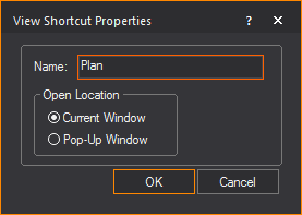
2In the Name box, type the new name of the shortcut.
3To open the shortcut in the current active window, enable the Current Window option button.
4To open the shortcut in a pop-up frame, enable the Pop-Up Window option button. For more information on pop-up frames, see “Pop-up frames”.
The properties of a Wireframe view affect how objects are drawn and how much information is visible. These settings are modified in the View Options.
1Ensure the Wireframe view that you want to modify is active.
2From the Options menu, choose View Options.
Result: The View Options window appears.
Tip: You can also use the View Options tool on the Standard toolbar to open the view options.
|
|
The View Options button. |
3Modify options as desired.
4Click OK.
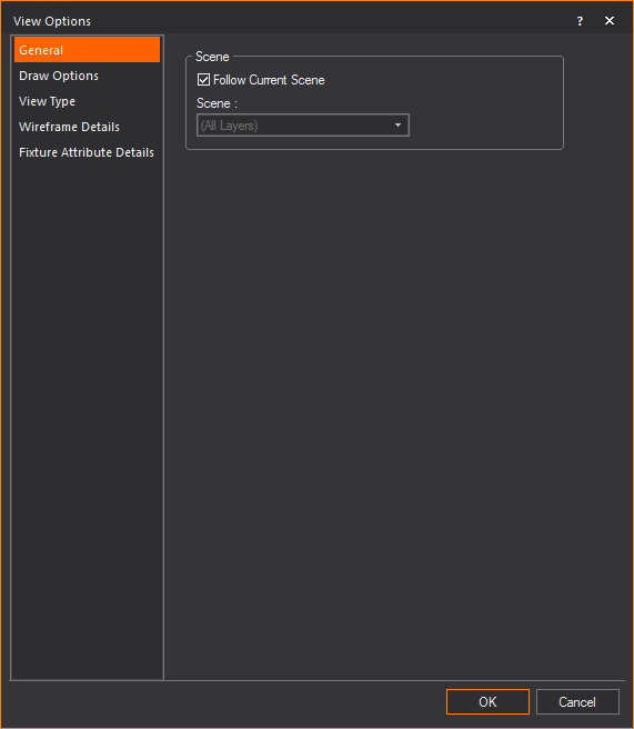
Options on the General tab affect the current scene.

nFollow Current Scene: Select this checkbox to use the currently selected scene. Clear this checkbox, and then select the desired scene from the Scenes drop-down list. To learn more about scenes, refer to “Editing objects”.
Tip: You can also change the current scene at any time by using the drop-down list on the Scene toolbar.
nScene: Name of the Wireframe view.
Draw Options tab
Options on the Draw Options tab affect the draw defaults. This tab is similar in function to the Draw Defaults tab available in Document Options. For more information on the Draw Options tab, see “Draw Defaults tab”.

nUse Document Settings: Select this checkbox to reference the options selected on the Draw Defaults tab of Document Options. Clear the Use Document Settings checkbox to make specific changes for the active view.
nGet Document Settings: Click this button to retrieve the values set on the Draw Defaults tab in Document Options.
Options on the View Type tab affect the plot type of the active view.

nView Type: The view types available. For information on view types, see “Plot types”.
Tip: The view type can be toggled using the tools on the CAD Options toolbar.
nScrollbars On: Select this checkbox to display the scrollbars on the bottom and left side edges of the Wireframe view. Clear this checkbox to turn the scrollbars off.
Options on the Wireframe Details tab affect what and how objects such as truss, text, point, library and other object information are displayed. This tab is similar in function to the Wireframe Details tab available in Document Options. For more information on the Wireframe Details tab, see “Wireframe Details tab”.
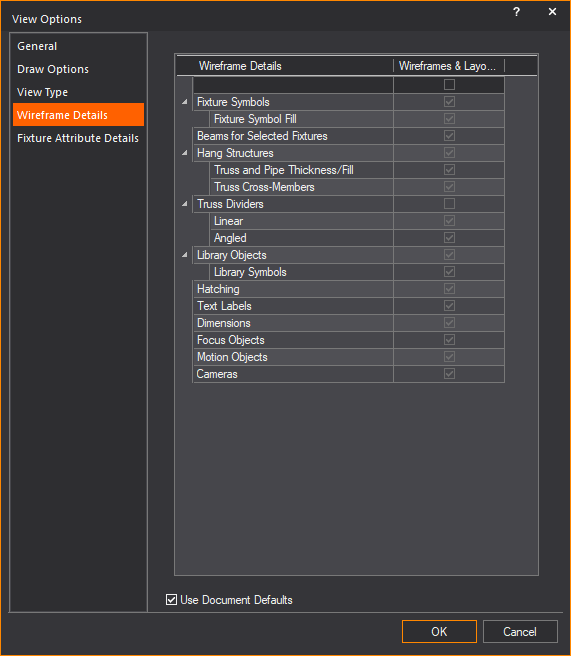
nUse Document Defaults: Select this checkbox to reference the options set in the Wireframe Details tab of Document Options. Clear the Use Document Defaults checkbox to make specific changes for the active view.
Options on the Fixture Attribute Details tab affect what and how fixture information are displayed. This tab is similar in function to the Fixture Attribute Details tab available in Document Options. For more information on the Fixture Attribute Details tab, see “Fixture Attribute Details tab”.
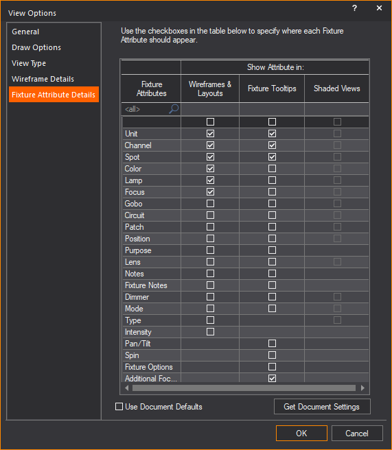
nUse Document Defaults: Select this checkbox to reference the options set in the Fixture Attribute Details tab of Document Options. Clear the Use Document Defaults checkbox to make specific changes for the active view.
nGet Document Settings: Click this button to retrieve the values set on the Fixture Attribute Details tab in Document Options.
Shaded or OpenGL views offer a 3D perspective view of your drawing. Surfaces, truss, and fixtures are “filled-in” or solid, rather than outlined as in Wireframe views.
Shaded views will follow scenes just like any other view.
To modify the point of view
nUse the arrow keys to move the position of the virtual target. PAGE UP/PAGE DOWN will zoom you in and out.
nAt any time you can use the SHIFT key in combination with any of the movement keys to move in smaller increments.
nThe mouse pan tool can be set to rotate the model or the camera around the target. You can also use the mouse wheel to zoom in and out. The arrow keys will continue to move the target position as you do this.
You can expand the Shaded view to encompass the entire screen by right-clicking anywhere within the view and selecting Open in Full Screen. To exit full screen mode, use the ESC key.
Note: The Full Screen Mode for Shaded view can be set to Windowed Full Screen Mode or Exclusive Full Screen Mode. See “Simulation tab” in the Application Options for details.
This section defines how a camera is controlled in Shaded view when Traditional WYSIWYG is selected as the Shaded View Camera Control. Traditional WYSIWYG is the default camera control in Shaded view.
In the Application Options window, you can choose Other 3D Applications on the Shaded View Camera Control drop-down list if you want to use camera control that complies with other 3D applications. See “Camera Control” for alternative mouse and keyboard action commands.
Note: The Camera-to-Target distance is maintained for all operations listed below. To change this distance, hold down simultaneously CTRL and ALT and spin the mouse wheel up or down while the Shaded view or the Shaded pane of Quad view is active. You need to perform this action to alter the Camera’s orbit; it also serves to set the target distance when rendering with Aperture enabled. This does not apply to Flying Cameras, since the target system for Flying Cameras is different than World or Standard Cameras’ target systems.
nHolding down the left SHIFT key on the keyboard while performing any of the actions below will decrease the speed at which changes are applied, regardless of how the actions are performed (i.e., by mouse or keyboard).
nHolding down the right SHIFT key on the keyboard while performing any of the actions below will increase the speed at which changes are applied, again regardless of how the actions are performed (i.e., by mouse or keyboard).
Orbiting the camera causes it to spin around its target without altering the target’s position. When the camera is orbiting, its own position changes. This control applies to World and Standard Cameras.
nTo orbit a Camera using the mouse, click and drag with the left mouse button in the Shaded view or the Shaded pane of Quad view.
nTo orbit a Camera by using the keyboard, hold down ALT and tap the arrow keys while the Shaded view or the Shaded pane of Quad view is active.
Notes:
nIn order to prevent accidentally changing the shape of Camera Paths, it is not possible to orbit Flying Cameras.
nThis is the “default” behavior for a Camera in WYSIWYG; it has not changed despite the introduction of the new camera system in Release 29.
Pivoting the Camera causes it to change its orientation/where it is pointing to (without altering its own position). Another way to think of it is that by pivoting the Camera, its target’s position is altered.
This control applies to World, Standard and Flying Cameras (at user-defined nodes).
nTo pivot a Camera using the mouse, hold down ALT on the keyboard and click and drag with the left mouse button in the Shaded view or the Shaded pane of Quad view.
nTo pivot a Camera using the keyboard, tap the arrow keys (without holding down ALT) while the Shaded view or the Shaded pane of Quad view is active.
Notes:
nThis is one of the two ways in which a Flying Camera can be modified at a user-defined node—dollying is the other.
nFlying Cameras cannot be pivoted at nodes where Behaviour was set to Follow Path or Follow Target. In cases where something is “interfering with the shot” and the Flying Camera at such a node must be pivoted, simply change the Behaviour at that node to user defined—the Camera’s current position and orientation will not be altered by the Behaviour change.
Dollying the Camera alters its own position and its target’s position at the same time. This control applies to World, Standard and Flying Cameras (at user-defined nodes).
nTo dolly a Camera up, down, left or right using the mouse, hold down CTRL and click-and-drag with the left mouse button in the Shaded view or the Shaded pane of Quad view.
nTo dolly a Camera in or out using the mouse, hold down CTRL and spin the mouse wheel up or down while the Shaded view or the Shaded pane of Quad view is active.
nTo dolly a Camera using the keyboard, hold down CTRL and tap the arrow keys while the Shaded view or the Shaded pane of Quad view is active.
nTo dolly a Camera in or out using the keyboard, hold down CTRL and tap the PAGE UP or PAGE DOWN keys while the Shaded view or the Shaded pane of Quad view is active.
Important: Dollying a Flying Camera will physically alter the shape of its Camera Path.
Notes:
nThis is the second of two ways in which a Flying Camera can be modified at a user-defined node—pivoting is the other.
nFlying Cameras cannot be dollied at nodes where Behaviour was set to Follow Path or Follow Target. In cases where something is “interfering with the shot” and the Flying Camera at such a node must be dollied, simply change the Behaviour at that node to user defined—the Camera’s current position and orientation will not be altered by the Behaviour change.
Rolling the Camera causes it to tilt left or right so that its bottom edge is no longer “parallel to the ground.” This control applies to all Cameras, at all times.
nTo roll a Camera using the mouse, click and drag left or right with the middle mouse button (i.e., the mouse wheel) in the Shaded view or in the Shaded pane of Quad view.
nTo roll a Camera using the keyboard, hold down ALT and tap the PAGE UP or PAGE DOWN keys while the Shaded view or the Shaded pane of Quad view is active.
Zooming the Camera causes its field of view to increase or decrease. This control applies to all Cameras, at all times.
nTo zoom a Camera using the mouse, spin the mouse wheel up or down while the Shaded view or the Shaded pane of Quad view is active.
nTo zoom a Camera using the keyboard, tap the PAGE UP or PAGE DOWN keys while the Shaded view or the Shaded pane of Quad view is active.
|
Action |
Traditional WYSIWYG |
Other 3D Applications |
|---|---|---|
|
Select a point |
With Selection Mode On, Left Mouse click |
Always (i.e. permanent Selection Mode On), Left Mouse click |
|
Selection box |
With Selection Mode On, Left Mouse click and drag; on Left Mouse button Up |
Always (i.e. permanent Selection Mode On), Left Mouse click and drag; on Left Mouse button Up |
|
Move camera along plane defined by initial camera axis as normal; target follows translation of camera |
Ctrl+Left Mouse drag/Right-click held during Left Mouse drag* |
Middle Mouse drag* |
|
Move camera around sphere with camera target at its center, target is fixed |
Left Mouse drag* |
Right Mouse drag* |
|
Pan camera along camera axis; target is fixed |
Ctrl+Alt+Scroll |
Scroll |
|
Pan camera and target along camera axis maintain distance between them |
Ctrl+Scroll |
Ctrl+Scroll |
|
Change Field of View |
Scroll |
Alt+Scroll |
|
Fine control modifier |
Shift |
Shift |
|
Roll Camera |
Middle Mouse drag |
Ctrl+Alt keyboard button+Mouse Right button pressed, and dragged |
|
Right-click menu |
Right Mouse button Down |
Right Mouse button Up if and only if no drag occurred between Mouse Down |
|
Camera pitch and yaw; camera axis rotates; camera target moves but maintains distance |
Alt+Left Mouse drag* |
Alt+Right Mouse drag* |
*Affected by View Option, “Pan tool moves objects”.
|
Action |
Traditional WYSIWYG |
Other 3D Applications |
|---|---|---|
|
Field of View |
Page Up/Page Down (unmodified) |
Always (i.e. permanent Selection Mode On), Left Mouse click |
|
Pan camera and target along camera axis |
Ctrl+Page Up/Page Down |
Always (i.e. permanent Selection Mode On), Left Mouse click and drag; on Left Mouse button Up |
|
Roll Camera |
Alt+Page Up/Page Down |
Ctrl+Alt+Page Up/Page Down |
|
Pan camera only along camera axis; target is fixed |
Ctrl+Alt+Page Up/Page Down |
Page Up/Page Down |
|
Camera pitch and yaw |
Arrow Keys (unmodified) |
Alt+Arrow Keys |
|
Move camera along plane |
Ctrl+Arrow Keys |
Ctrl+Arrow Keys |
|
Move camera around sphere |
Alt+Arrow Keys |
Arrow Keys |
|
Fine control modifier |
Shift |
Shift |
Creating a camera from shaded view
If you have set up a “perfect shot” in the Shaded view, you can quickly and easily save the view to a camera.
To place a camera at a specific location, you must draw it in Wireframe; for information on drawing cameras, see “Drawing cameras”.
To create a camera from shaded view
1In the Shaded view, use your mouse to arrange the view that you want to see.
2Once you are satisfied with the viewpoint, right-click on the Shaded view and select Save View as New Camera.
Tip: Alternately, on the Camera toolbar, you can click the Save View as New Camera icon.
|
|
The Save View as New Camera button. |
3In the window that appears, type a name for the new camera, and then click OK.
Result: The camera is now available from the Current Camera drop-down list on the Camera toolbar.
After you have drawn a camera, you can use the Camera toolbar in Shaded views to view your drawing through the camera of your choice.
You can also use this toolbar to quickly access the camera Properties page and change properties, such as the camera name and field angle, and to lock the camera in place so that you cannot accidentally move it. For details, see the procedures on the next page.
Finally, the Camera toolbar also enables you to quickly insert a camera directly from the Shaded view, based on the current viewpoint. For details, see “To create a camera from shaded view”.

To switch to a camera using the camera toolbar
1In CAD, DESIGN, or LIVE mode, click the Quad or Shaded tab.
2Right-click in the toolbar area and select Camera.
Result: The Camera toolbar appears.
3From the Current Camera drop-down list, select the camera through which you want to view your model.
Note: To switch back to the default view, select World, and then click the Reset Camera button to reset the view.
Result: The viewpoint switches to reflect that of the currently selected camera.
Follow the steps below to lock a Camera in its current position in the Shaded view. This feature helps prevent you from accidentally moving or zooming a camera while adjust the viewpoint in the Shaded view.
1In CAD, DESIGN, or LIVE mode, click the Quad or Shaded tab.
2Right-click on the toolbar area and select Camera.
Result: The Camera toolbar appears.
3From the Current Camera drop-down list, select the camera that you want to lock in position.
4On the Camera toolbar, click the Camera Lock icon.
|
|
The Camera Lock button. |
Result: The Camera is now locked in position in the Shaded view. Whenever you select this camera and attempt to adjust the viewpoint in the Shaded view, a lock symbol appears in the middle of the Shaded view. To unlock the Camera, simply select it from the Camera toolbar, and click the Camera Lock icon again.
To use the pitch, roll and yaw locks for rotations
Use the Lock-X, Lock-Y, and Lock-Z buttons on the Camera toolbar to prevent in-place rotations along the specified axis:

nLock-X, or Rotation around the X Axis = PITCH [tilting forward and backward]
nLock-Y, or Rotation around the Y Axis = ROLL [tilting side to side]
nLock-Z, or Rotation around the Z Axis = YAW [also called Heading or Direction]
To see the effect of these locks in the Shaded view, you must press ALT while dragging the view; these locks have no effect if you do not press ALT.
Note: Click the reset buttons (Rx, Ry, Rz) to re-orient the camera to the world's axes.
Switching cameras in shaded view
Camera objects drawn in Wireframe are visible in Shaded view to indicate position and orientation.
Note: In Shaded view, you must select Display Model and Display Tooltips on the Camera tab of the View Options window to see and switch cameras in Shaded view. Switch To This Camera is disabled if Display Model and Display Tooltips are not selected.
To switch cameras in shaded view
1On Shaded view, hover over the Camera you want to select.
Result: The Camera is highlighted and shows tooltip information.
2Right-click on the Camera and choose Switch To This Camera from the menu that appears.
Result: Shaded view displays the view angle from the selected Camera.
To help you quickly switch from one Camera to another, Number/Numpad keys 1 through 9 are now automatically assigned to new Cameras as you create them.
Hotkeys are assigned in ascending order (starting with 1 for the first Camera you create, 2 for the next one, and so on, all the way to 9).
1On the number pad of your keyboard, ensure that the NUM LOCK is activated.
2In WYSIWYG, click to view your drawing in a Shaded view.
3On the Number Pad of your keyboard, use the numbers associated with the Cameras in your drawing to switch quickly from one Camera to another.
Tip: Use the 0 key to quickly reset the Camera toolbar drop-down list to World camera, then click the Reset button to reset to the default Camera World view.
To change or delete the camera hotkey assignment
To change or delete the hotkey assignment for a Camera, complete the following steps.
1Select the Camera, right-click, and select Properties.
2Click the Camera tab.
3Select the new hotkey from the Assigned Hotkey drop-down list; to remove a hotkey assignment, simply choose None from the same drop-down list.
4Click OK.
Note: Hotkey assignments can be set and changed in the Camera Manager window, see “Camera Manager”.
Creating an image from shaded view
When you have positioned the camera in Shaded view, you can export the view as an image stored in your computer.
To export an image from shaded view
1Right-click on the Shaded view and select Export to Image.
Result: The Shaded View Image Export window appears.
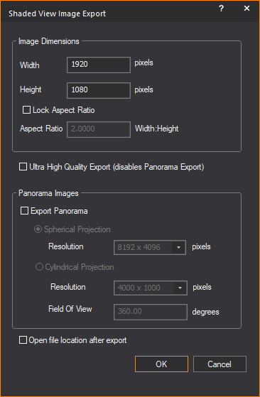
2In the Image Dimensions section, use the appropriate boxes to adjust the height and width of the image.
The height and width correspond to the current dimensions of the Shaded view.
3Select the Lock Aspect Ratio checkbox to lock the aspect ratio of the dimension. Type the new value in the Aspect Ratio box to change the aspect ratio.
4WYSIWYG enables the Ultra High Quality Export checkbox if an 8GB (or more) graphics card is detected.
Select the Ultra High Quality Export checkbox to export the Shaded view to a higher fidelity image (with better defined and crisper beams, less aliasing on shadows, etc.) than what appears in the Shaded view. See below the image comparison between Ultra High Quality Image Export and High Quality Image Export.

Note: Selecting the Ultra High Quality Export checkbox disables the Export Panorama option.
5In the Panorama Images section, select the Export Panorama checkbox to export a panoramic image of your Shaded view and enable the projection options.
Note: The maximum resolution of an image for export is 8192 x 4096 pixels if WYSIWYG detects the user’s computer video card has enough Video Memory to support a large panorama image. Regardless of how much Video Memory is available, it is not possible to export Ultra High Panorama Images.
6Select Spherical Projection to export the panoramic image as a Spherical image showing up to a full 360 degrees camera view that includes top and bottom.
Or select Cylindrical Projection to export the panoramic image as a Cylindrical image showing up to a full 360 degrees camera view of the sides only.
7Select the image display quality in pixels from the Resolution drop-down list of the selected option.
8In the Field Of View field, type the maximum panoramic angle for the image.
9Select the Open file location after export checkbox to launch the exported file after saving.
10Click OK.
11Select a file name, location, and file type, and then click Save.
Notes:
nA file name template can be specified in Shaded View Export Options in the File Options tab of the Application Options window.
nAlternately, a file name is automatically assigned using smart variables, which is also defined in Shaded View Export Options in the File Options tab in the Application Options window. See “File Options tab”.
The properties of a shaded view affect the view point, fixture beam quality, and ambient light. These settings are modified in the View Options.
1In Shaded view, from the Options menu, choose View Options.
Result: The View Options window appears.

Tip: You can also use the View Options tool on the Standard toolbar to open the view options.
|
|
The View Options button. |
2Modify options as desired.
3Click OK.
Options on the General tab affect the scene that is displayed in the Shaded view.

Scene
nFollow Current Scene: Select this checkbox to use the scene that is displayed in the drop-down list on the Scene toolbar. Clear the checkbox, and then select the desired scene from the Scene drop-down list. For more information about scenes, see “Scenes”.
Tip: You can also change the current scene at any time by using the Scene toolbar.
nShaded View Profile: Previously created Shaded View Profiles can be enabled from the drop-down list. For more information, see “Shaded view profile”.
Resolution: These options allow you to set the maximum resolution at which the Shaded view appears within the Shaded view layout tab or within the Shaded pane of the Quad layout tab or a Custom layout tab. This will be the resolution at which the Shaded view will record or output via NDI, without letterboxes or pillarboxes, unless the Output Entire Pane option is selected in the Shaded View Output tool.
nMaximum Resolution (Camera Aspect Ratio Ignored): Select this checkbox to enable the options for Width, Height, and Lock Aspect Ratio to Width:Height. Maximum Resolution is defined by Width and Height, or by Width and Aspect Ratio.
When Maximum Resolution (Camera Aspect Ratio Ignored) is selected, all settings in the Resolution section will override the Aspect Ratio defined for the current Camera and all Cameras (World, Standard, or Flying). The Shaded view will conform to the resolution defined in this section.
nWidth: Type the pixels to set the horizontal dimension of your Shaded view resolution. (100 to 9999)
nHeight: Type the pixels to set the vertical dimension of your Shaded view resolution. (100 to 9999)
nLock Aspect Ratio to Width:Height: Select this checkbox to define an aspect ratio and enable the Aspect Ratio Width:Height field.
nAspect Ratio Width:Height: Type a value in this field to define an aspect ratio. WYSIWYG will automatically calculate and display the Maximum Resolution Height. This field accepts values from 0 to 99 and up to four decimal places.
Notes:
nIf Maximum Resolution is smaller than the Shaded pane, the Shaded view output will appear with pillarboxes and letterboxes.
nIf Maximum Resolution is larger than the Shaded pane, the Shaded view output will appear with pillarboxes only OR letterboxes only and smaller than what is defined.
nTo change the color of letterboxes and pillarboxes, see “Camera tab”.
nSimulation Information and Visual References will appear within the Shaded view output (i.e. record or NDI stream) if any of these options were enabled.
nMaximum Resolution will appear as the View Resolution label when View Statistics is enabled and displayed.
nThe Maximum Resolution settings will be saved with the Shaded View Profile. Different Shaded View Profiles will allow different Maximum Resolution settings. Maximum Resolution can only be used within layout tabs or Shaded View Popup windows (i.e. not in Full Screen mode).
Tips:
nYou can output or record everything that is displayed in the Shaded Pane, which includes the Shaded view and all the view options enabled (Gyroscope, View Statistics, Simulation Information, Visual References, etc.). For information on recording the Shaded Pane, see “Shaded view output”.
nIn complex files that are subject to fillrate bottlenecks (where Shaded view performance is low due to the video card not able to render and display frames on-screen fast enough), setting a lower Maximum Resolution may improve performance.
View Styles: These options allow you to define how the Shaded view appears.
Note: These options do not impact the Shaded view performance.
nObject Bounding Boxes: Select this checkbox to show green bounding boxes around all objects in the scene. This view style was designed to be used in conjunction with the Consolidated Mesh feature (for details see “Consolidated mesh”) and enables you to visually analyze an object’s complexity.
nDisabled Textures: Select this checkbox to hide (not remove) all textures used in a scene. This option is useful when verifying why a particular texture doesn’t seem to sit properly on an object and you want to check the underlying native texture and geometry for anomalies. This option is also useful when checking if a Normal Map is correctly applied to geometry.
nDisabled Normal Maps: Select this checkbox to hide (not remove) all Normal Map textures used in a scene. This option is useful when the visual effect created by Normal Map textures does not need to be visualized.
nWireframe Geometry: Select this checkbox to display all objects in a scene (except beams) as wireframe outlines instead of solids. This feature helps you analyze the complexity of a scene so you can alter objects as necessary to speed up rendering times and minimize file size. For example, when you see complex objects in your file (those shown with a high-density wireframe), you can optimize them by reducing their polygon counts, either with the Consolidated Mesh feature or by re-importing a less complex version.
nSketch: Select this checkbox to display the Shaded view in freehand drawing style. The Sketch view style shows the basic drawing outline of 2D and 3D objects in black over white background. Selecting Sketch enables the Invert option.
nInvert: Select this checkbox to reverse the Sketch view style to show the drawing outline in white over black background.
Notes:
nNo lighting visualization such as Beams, Footprints, and Flares will display when Sketch is selected.
nThe Sketch view style requires to enable Deferred Rendering in the Simulation tab of the Application Options window. It is not possible to enable Sketch if Deferred Rendering is disabled. For more information on Deferred Rendering, see “Simulation tab”.


Simulation Information: These options allow you to define how simulation information is presented.
nView Statistics: Select this checkbox to see information about the scene in the upper-left corner of the Shaded view. Note that enabling this view style will not modify the look of the scene. The information displayed is based on the layers and/or scene that are enabled. The following statistics are displayed:
FPS: The frame rate (frames per second) as the Shaded view is altered by moving the image with your mouse (which affects the fixtures in your file), changing Looks in DESIGN mode, or by incoming DMX in LIVE mode. Note that when the Shaded view is static (as it is most of the time), the FPS field displays “n/a”.
Video Memory: The video memory capacity.
Deferred Shading: The Beam quality setting.
Volumetric/Enhanced Beams: The Beam simulation mode selected.
Camera Resolution or View Resolution: Shaded view output resolution. Camera Resolution appears if Camera Aspect Ratio is used and View Resolution if Maximum Resolution is used. The text color will appear in WYSIWYG orange if the Shaded view output resolution is bigger than Shaded pane resolution.
Window Resolution: Shaded pane resolution.
Objects: The total number of visible objects.
Fixtures: The total number of visible fixtures.
Beams: The number of beams currently appearing in the Shaded view. Note that it is normal for the number of beams to be different from the number of fixtures. For example, a three-cell Cyc fixture will count as a single fixture, but when all three cells are on, the number of beams will read “3”.
Glowing Screens: The number of screens and LED walls currently appearing in the Shaded view.
Lighting Complexity: The complexity of the Shaded view. The four complexity levels - low, medium, high, and very high are meant to help you understand how complex the current scene is. When the complexity level is high or very high, it is strongly recommended that you consider optimizing the file. For example, you could use the Consolidate Mesh feature to reduce the number of polygons in a highly-detailed model. See “Consolidated mesh”.
Quality [Manual]: Shaded view performance setting.
System Memory Used: The system memory currently used.
Video Recording: On/Off: Shaded View Output recording On or Off.
nPerformance Graph: Select this checkbox to view a performance graph in Shaded view.
nCamera Information: Select this checkbox to view information in Shaded view about the Cameras that you have drawn.
Visual References: These options allow you to define how visual references are presented.
nWorld Grid: Select this checkbox to show the World Grid in Shaded views.
nWorld Axis: Select this checkbox to show the World Axis in Shaded views.
nGyroscope: Select this checkbox to show the Gyroscope in Shaded views. The Gyroscope allows for continuous orientation monitoring while moving around in Shaded view.
nWireframe Selection: Select this checkbox to highlight fixtures selected in Wireframe view when the view is switched to Shaded view.
nFixture Tooltips: Select this checkbox to display the specific information about a fixture when you hover over it in Shaded view.
Options on the Simulation tab affect the view point, beam quality, and ambient light levels.

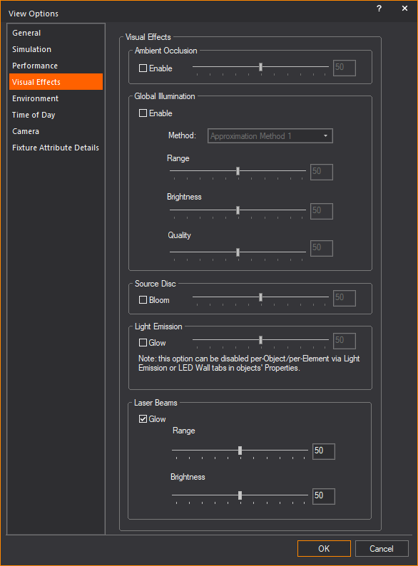
nAmbient Light: Use the slider to increase or decrease the amount of ambient light level shown in the Shaded view. The percent box indicates the degree of ambient light you have chosen.
nAmbient Color: Modifies the color of the ambient light. For example, use this feature if you'd like the Ambient light in your file tinted yellow or blue to match the type of house lighting in your venue. By default, the Ambient Color is set to white.
nBackground Color: Modifies the background color used in the Shaded view. This color is visible when you zoom far enough away that you can see beyond the venue.
Quality: The options in this section control the degree to which you want to emphasize beam quality over performance.
nMode: Choose one of the following beam simulation modes. Note that when you select this value, and then choose the beam control options, you will automatically see the results in the Shaded view, enabling you to adjust them as necessary before you click OK to save your changes:
Enhanced: Enhanced is the default beam mode. Select to enable enhanced beam control options affecting beam quality.
Volumetric: Volumetric mode delivers higher quality visualization of beams than enhanced beams. Improved lens flair effects and beam throws are just some of the noticeable improvements. Due to the required system resources need to run Volumetric beams, system performance may be effected depending on system running WYSIWYG.


Note: Deferred Rendering is required to run Volumetric Beams. If this option is not available, it means the graphics card on your computer does not support Volumetric beams.
nDetail: Use the slider to increase or decrease the level of details displayed in Volumetric mode. An increase in details will result in a decrease in performance. The default detail setting is 0.
Note: For most users, an increase in detail will not be noticeable, except in certain camera positions and situations.
Tip: You can use the per fixture Detail slider in the Properties of a selected fixture only, to minimize the effect on performance. For more information on the Detail option per fixture, see the “Fixture-specific properties” section.
nBeam: Lower beam quality affects the beams’ footprint, sometimes making them appear blurry. While it is recommended that this value be set to High, if you notice a reduction in performance, particularly when viewing a complex scene with many moving lights, you can increase performance by lowering the quality to Medium or Low. Note that if you find it necessary to use Low quality for acceptable performance, it is recommended that you upgrade to a more powerful system.
nEnhance Projected Video: This option is available only when High Beam Quality is selected. It should only be used when video is being projected, not when video is being used on a Screen, Surface, Object, or LED Wall. Enabling this feature decreases Shaded view performance, but increases the visual quality of the footprint (video) created by the projector.
Brightness: Use the Brightness sliders (or type a value in the corresponding box) to control the visual brightness of beams, footprints, and lens flares.
Every fixture/bulb in the WYSIWYG library has “brightness value” defined in its properties. The “brightness value” of a fixture/bulb is the relative intensities between light beams from different fixtures based on their published photometric data.
The Beam, Lens Flare and Footprint sliders will alter all beams relatively in comparison to all the fixture beams in the scene. For example, you can see this when a bright fixture is hung beside a fixture that is less bright. (i.e. 10” Fresnel with 2KW bulb is hung beside a 6” Fresnel with 500W bulb, both at full intensity). The relative brightness between both fixtures matches the difference in intensity from both fixtures with reference to their published photometric data.
A scene with many lights may be better visualized when some of the beams’ components are less bright. Note that brightness settings affect all beams in the scene equally and are for aesthetic purposes only; the sliders are not connected to the fixtures’ intensity.
The Brightness sliders enable you to balance the brightness values for different scenes, each scene varying based on the density and intensity of its fixtures. These values are saved into the scene file and will, therefore, change when new scenes are loaded.
Note: The default value of 50 is the baseline value generated by the values from the library definitions. If the scene does not show any beams or footprints, ensure that none of the brightness sliders is set to zero.
nBeam: Controls the brightness of the beam cone. A scene with many overlapping beam cones will tend to saturate, which can be reduced by decreasing the brightness.
nFootprint: Controls the brightness of the beam footprint. A scene with many overlapping footprints will tend to saturated, which can be reduced by decreasing the brightness.
nLens Flare: Controls the brightness of the lens flare, which is the dominant visual effect when the camera is aimed directly into a fixture’s lens. In addition, when you are behind a fixture that is directed away from the camera, the lens flare component is used to create a simulated beam cone.
nBeam Exposure: Use this slider to adjust the overall exposure of the beams. The default value is 50 which is the baseline value generated by the values from the library definitions. Increasing the exposure causes all beams in the scene to become brighter exponentially. This may be required if you feel all beams seem too dim. Decreasing the exposure causes all beams in the scene to become dimmer exponentially. This may be required if you feel all beams seem too bright/saturated. If you wish to correct the relative brightness of one fixture, it is best to adjust its beam brightness by going into Fixture's properties and using the Beam Intensity Multiplier on the Beam Options tab.
Note: Beam Exposure works similar to the exposure control of a camera but the values are not based on the F-stop. The fixture’s output is affected relatively; and beam, footprint and flare are all affected at the same time. For example, when you adjust the exposure of two Fresnels at full intensity - a 10” and a 6”:
nWhen increasing, the beam, footprint and flare of the 10” fresnel stops getting brighter at a value of about 95, but the value from the 6” fresnel goes up to 100.
nWhen decreasing, the 6” fresnel stops getting dimmer at around 20, but the value from the 10” fresnel goes down to 0.
nScattering: Use this slider to enable and control the simulation of the light energy that deflects and scatters when passing through the imperfect medium of air filled with various particles/molecules. Light is deflected off of its straight path and scatters in many directions.
Use the Scattering slider to increase or decrease the scattering effect. When Scattering is set to 0, no scattering effect is applied to the light beam from a selected fixture.
When Scattering is enabled, the intensity of the light beam from a fixture appears to vary when viewed from different angles.
Note: By default, Scattering is only available when the Simulation Quality is set to Volumetric mode.
Shadows
nEnable: Select this checkbox to display shadows. Turning Shadows on creates a more realistic Shaded view, but adds extra complexity, which may also slow down performance as more calculations are required.
nSoft Shadows: Select this checkbox to display higher quality soft shadows. Use this option to soften the shadows for best visual quality, for example when capturing a screenshot of a look.
Note: Enabling Soft shadows while running cues in LIVE mode is not recommended, as it will drastically slow down performance.
Alpha Beam Shadows
nEnable: Alpha Beam Shadows in Shaded view is enabled when Volumetric Beam quality is selected. Select Enable checkbox to display Alpha Beam Shadows.
nNum. Levels: Select the number of levels to be calculated for Alpha Beam Shadows from this drop-down list.
For example, if you select 2 from the drop-down list, a beam’s color and intensity will be calculated based on alpha levels only that pass through 2 surfaces, and any additional surfaces with alpha levels will be ignored as the beam will just pass through them.
Note: Each Alpha shadow level supported for this feature requires additional video memory from your graphics card, and can impact performance, depending on your scene and computer hardware.
Footprint
nHot Spot: Select this checkbox to display hot spots. Hot spots are usually noticeable with conventional fixtures, which have lenses that refract the beam non-uniformly; the center of the beam is bright and it gradually drops off moving outward to the edge of the beam. Conversely, the majority of automated fixtures have a different type of lens that corrects the beam refraction to have a more uniform footprint.
nFootprint Focus: Select this checkbox to enable footprint focus functionality. Enable this option to visualize the footprint focus, otherwise, fixtures for which you have defined footprint focus will not display. This toggle also offers an easy way to turn off the display of the footprint focus when not needed (for a performance boost) without losing the footprint focus settings of the fixtures.
nFocus Lines: Select this checkbox to enable the display focus lines, when the Footprint Focus option is enabled for conventional fixtures in CAD mode (fixture's Properties) and/or automated fixtures in DESIGN mode (Footprint Designer tool).
Materials
nEnable: Select this checkbox to enable materials functionality. When a material is applied to an object, it affects how the object interacts with light. This interaction is visible in Shaded view and in rendered images from the WYSIWYG Render Wizard.
nReflections: Select this checkbox display reflections on materials. When a reflection is applied to an object, it will reflect light depending on the material settings. This interaction is visible in Shaded view and in rendered images from the WYSIWYG Render Wizard.
Screen/LED Wall Glow
nEnable: Select this checkbox to toggle a glow that will emit from screens and LED walls, increasing the realism of visualizations. When enabled, use this slider to adjust the intensity of the glow.

Options on the Performance tab are features that let you manage between system efficiency and visual quality.

Adjust FPS (This option is for Volumetric Beam Mode only): You can adjust the quality of the Shaded view visualization within the parameters of High and Medium qualities that were set in the Simulation tab. Lowering the quality will increase performance.
nSet Quality to: Select this radio button to specify the level of visualization quality of the Shaded view which WYSIWYG will maintain. Select the percentage quality from this drop-down list.
When the Set Quality to option is selected, its drop-down list is enabled and the Auto-Adjust option is disabled. When the Auto-Adjust option is selected, the Target FPS and Min. Quality drop-down lists are enabled and the Set Quality to option is disabled. By default, the Set Quality to option is enabled and the drop-down list is set at 80.
nAuto-Adjust: Select this radio button to allow WYSIWYG to attempt to maintain a consistent frames per second when visualizing. WYSIWYG achieves this by reducing the quality of the Shaded view image to increase performance.
nTarget FPS: Select the desired amount of frames per second which WYSIWYG will attempt to maintain from this drop-down list.
nMin. Quality: Select the minimum level of visualization quality which WYSIWYG will attempt to maintain from this drop-down list.
Notes:
nThe Adjust FPS options only work with Volumetric Beams with Enhanced Beams, Adjust FPS set to off. In the View Statistics, this is displayed with View Resolution being set to N/A.
nWhen you select Auto-Adjust, you are permitting WYSIWYG to vary the Shaded view resolution automatically - as needed - to deliver the highest frame rate possible on your computer.
Objects: You have the option of improving performance by adjusting how these three object types are displayed:
nDraw Hang Structures: Select this checkbox to draw pipe and truss objects in Shaded view. If you clear this checkbox, pipe and truss objects will not appear in Shaded view, which will reduce the amount of geometry being drawn in Shaded view and improve performance.
nDraw Fixtures: Select this checkbox to draw the fixture body in Shaded view. If you clear this checkbox, the fixture body will not be drawn in Shaded view, only the beam, which will reduce the amount of geometry being drawn in Shaded view and offer slight performance improvements.
nEnhance LED Walls: Select this checkbox to improve the visual appearance of LED Walls. If there are many large LED Walls in the document, then performance may decrease as a result of having enabled this option; turn this option off and check whether performance improves.
Show Footprints/Shadows: You have the option to show footprints and shadows in the Shaded view for one or more of the following two object types:
nHang Structures: This option controls whether hang structures like pipes and truss will cast shadows and receive footprints in the Shaded view. It is extremely useful for checking effects or looks such as truss warmers, but it is recommended to keep this option disabled in order to increase performance.
nAll: Select this radio button to display in Shaded view the footprints/shadows of all the hang structures in your drawing.
nEnabled Only: The footprint/shadow of a hang structure object appears in Shaded view only when the Cast Shadow option in the Appearance tab of its Properties window is enabled. Select this radio button to display in Shaded view only the footprints/shadows of hang structures with enabled Cast Shadow feature.
nFixture Bodies: This option controls whether the bodies of fixtures will cast shadows and receive footprints. This feature is useful when checking to see if certain fixtures are blocking the beams of other fixtures, but it is recommended to keep this option disabled in order to increase performance.
nAll: Select this radio button to display in Shaded view the footprints/shadows of all the fixtures in your drawing.
nEnabled Only: The footprint/shadow of a fixture appears in Shaded view only when the Cast Shadow option is enabled in the Appearance tab of its Properties window. Select this radio button to display in Shaded view only the footprints/shadows of fixtures with enabled Cast Shadow feature.
Note: By default, the Cast Shadow option is disabled on a hang structure and a fixture when created in your drawing; on the other hand, all objects have the Cast Shadow option enabled by default.
nFixture Settings: Click this shortcut button to open the Fixture Settings tab in the Document Options window.
Options on the Visual Effects tab are visual effects that can be added to enhance visualization.
Ambient Occlusion: Adds shadows where pieces of geometry intersect at various angles (most visibly in corners) by calculating the amount of ambient light that reaches those intersections, making visualization more realistic.
nEnable: Select this checkbox to use the slider to adjust the amount of Ambient Occlusion. You may type the value in the adjacent box.


Global Illumination: Simulates the indirect illumination of light bouncing off of geometric surfaces onto other surfaces.
nEnable: Select this checkbox to activate the Global Illumination settings.
nMethod: Determines how object are illuminated. Approximation Method 1 illuminates objects from all directions. Approximation Method 2 illuminates only the visible sides of an object.
nRange: Determines how far illumination will travel from objects.
nBrightness: Determines how luminous objects will appear.
nQuality: Determines the quality of light illuminated from the object.

Source Disc: Creates a halo of light around a fixture's aperture to simulate light diffusion for very bright sources.
nBloom: Select this checkbox and use the slider to adjust the size and brightness of the Source Disc from fixtures in Shaded view. You may type the value in the adjacent box.

Light Emission: Creates a glow effect from objects for which Light Emission has been enabled to simulate light emitting from light boxes, projection screens, etc.
nGlow: Select this checkbox and use the slider to adjust the glow effect from the light emitting objects in Shaded view. You may type the value in the adjacent box.
Light Emission is enabled in the Light Emission tab of the object’s Properties window.

Note: This option can be disabled per-Object/per-Element via Light Emission or LED Wall tabs in objects’ Properties.
Laser Beams: Creates the glow effect from the beams of lasers in a scene.
nGlow: Select this checkbox to enable and adjust the Range and Brightness of the glow effect from laser beams.
nRange: Use the slider to adjust the length of the glow effect from the laser beam.
nBrightness: Use the slider to adjust the intensity of the glow effect from the laser beam.
Note: This setting is not to be confused with the intensity/brightness of the laser beam itself, which may be adjusted from the laser fixture’s Properties > Fixture > Beam Options tab (by modifying the Beam slider).
Options on the Environmental tab control non-uniform atmospheric effects in beams.
Smoke Simulation: Beams can display non-uniform atmospheric effects in their beam cones.
nSmoke Density: Select this checkbox to display a non-uniform smoke suspension in the beam cone, which also enables Animate Smoke and Turbulence. Use the slider to change the density of the smoke.
nAnimate Smoke: Select this checkbox to make the non-uniform smoke move, and then specify the direction and speed using the X, Y, Z sliders.
When the slider is in the middle at 0, smoke will not be animated in that axis. Move the slider off 0 to animate the smoke in that direction. The further away the slider is from 0, the faster the smoke will travel.
For example, to make the suspended smoke move in an upward direction to simulate a rising smoke effect, move the Z slider to the positive (right) side of 0, leaving the X and Y sliders at 0. To increase the speed at which the smoke is rising, move the slider further along on the positive scale.
nTurbulence: Select this checkbox to display atmospheric smoke effects and low-lying ground smoke or fog effects with irregular and turbulent flow.
Turbulence is enabled when Volumetric Mode is selected in the Quality section in the Simulation tab of the View Options window.
Turbulence is disabled when Enhanced Mode is selected in the Quality section in the Simulation tab of the View Options window.
Ground Smoke
nEnable Ground Smoke: Select this checkbox to display low-lying ground smoke or fog effect, and enable its properties for changes.
nBase Height: Specify the height of the horizontal bottom plane of the ground smoke from the floor of the drawing where Z coordinate is at 0.
nHeight: Specify maximum height of the ground smoke when it rises from its horizontal bottom base.
nVariance: Use the slider to increase or decrease the maximum peaks and troughs of the ground smoke turbulence. You may type the value in the adjacent box. The ground smoke will be displayed without turbulence if the slider is set to the minimum at 0. The ground smoke turbulence will be displayed with maximum peaks and troughs when the slider is set to the maximum at 100.
nIntensity: Use the slider to increase or decrease the brightness of the ground smoke or fog. You may type the value in the adjacent box.
nEdge: Use the slider to show a softer or harder ground smoke edge. Increase the slider to show a more defined smoke edge. Decrease the slider to show a less defined and fuzzier outline of the smoke edge. You may type the value in the adjacent box. See below example images showing Ground Smoke Edge at 40 and at 75.

Just as you can simulate time of day/outdoor lighting when setting up your renderings in the Render Wizard, you can achieve the same effect in the Shaded view in real time for all events that take place outside. Just like when you are setting up a rendering, in order to achieve the correct outdoor lighting conditions in the Shaded view, you must define the geographical location for your event and set the direction North. For details, see “To draw a compass”.
nEnable Time of Day Lighting: Select this checkbox to consider outdoor lighting conditions in the Shaded view, and then specify the lighting conditions below. The Shaded view adjusts accordingly, in real time.
nDate: The date determines the position of the sun and/or moon and the resulting amount of light available. Type the date when the event will take place.
nTime: The time determines the position of the sun and/or moon and the resulting amount of light available. Type the time when the event will take place.
nEnd: Select this checkbox if you want to specify an end time for the event, and then type the date and time in the boxes provided.
nTimeline: By defining Start and End Dates/Times, you can check lighting conditions between those times. Use the Timeline slider to adjust the current Shaded view time.
nSky Conditions: The amount of light available determines the brightness of the resulting image in the Shaded view. Use the Sky Conditions slider to adjust the quality of light (cloudy or clear).
nEnable soft shadow: Select this checkbox, and then use the slider to set the softness of shadows that are created by sunlight. The softer the setting, the less sharp the resulting shadow.
nRegional Settings: Click to set the geographic location of your show. You can either select the country and city or enter the latitude and longitude of the location. These settings are used in Shaded views and renderings that use environmental options.
Options on the Camera tab affect the Cameras in your file.

nCamera: Select a camera from the drop-down list to change the point of view.
Notes:
nTo display the original point of view and remove any previous association with a camera, select World camera, right-click on the Shaded view and click Reset Camera from the menu that appears.
nReset Camera menu applies only if World is the selected Camera. Reset Camera menu is greyed and unavailable if a drawn camera is selected as the current camera.
nYou can also control the camera view point with the Camera toolbar. For information on using the Camera toolbar, see “Using the camera toolbar”.
nPan tool moves objects: Select this checkbox if you want to rotate the model on the target. Clear this checkbox if you want the pan tool to rotate the camera around the target. You can use the right, left, up, and down arrow keys in addition to the mouse button to pan to the desired location.
Camera Path
nFollow Camera Path playback: Select this checkbox if you want to lock the Shaded view to the Camera Path’s camera view whenever the Camera Path is playing.
Fixture FOV
nDisplay Information of Selected Fixture: Select this checkbox to display information about the selected fixture at the bottom of the view.
This option becomes active when the Camera drop-down list is set to POV of selected fixture, and only works if one fixture is selected. (When multiple fixtures are selected, the camera reverts to its previous camera setting and no fixture information displays).

Camera Target
nDisplay Target: Select this checkbox to show the focus point of the selected camera in the Shaded view. Choose the color of the displayed target by clicking the Color box, and then selecting the color from the resulting palette. The target is only visible in Shaded view.
nInfinite Lines: Select this checkbox to show the camera target lines of the selected camera in the Shaded view, extending the camera target lines to infinity.
Letter/Pillar Box
nColor: Select from the Color box the color for the letter or pillar box that will be displayed to indicate the viewing definition boundaries.
Camera Model
n Display Model: Select this checkbox to show drawn camera objects in Shaded view. A camera object that is selected in Wireframe view will also display the outline frame of its POV in Shaded view.
nDisplay Tooltips: Select this checkbox to show the camera name and camera information when you hover over the camera in Shaded view.
You must select the Camera Information checkbox on the Simulation Information section on the General tab of the View Options window to show camera information in Shaded view.
Note: The camera object and camera information also appear in virtual reality mode to help you identify the camera position, viewing angle, and other information.
Options on the Fixture Attribute Details tab affect which attributes of the fixture are displayed with the fixture object in Shaded view.

nFixture Attributes: Select the attributes that you want to display around the fixture symbols. To modify how the attributes are laid out, refer to Fixture Notation and Information Layout in “Fixture notation”.
nShaded Views: Select the checkboxes corresponding to the attributes that will appear when your cursor hovers over a fixture in Shaded view.
Tip: Select the checkbox on the top row of the Shaded Views column to select all checkboxes below.
Note: The columns under Wireframes & Layouts and Fixture Tooltips are greyed because they are not applicable in Shaded view.
nUse Document Defaults: Select this checkbox to reference the options selected on the Wireframe Details tab of Document Options. Clear the Use Document Defaults checkbox to make specific changes for the active view.
nGet Document Settings: Click this button to retrieve the values you have set on the Shaded Views column of the Fixture Attribute Details tab in Document Options.
The footprint technology of the beam simulation in Shaded view calculates footprints using color modulation, which is based on color theory. When a light beam strikes an object, some of the light is absorbed and some is reflected. The reflected color that the human eye can see is a subset of the source light spectrum that was not absorbed by the object.

For example, when a red light is shining on a blue riser, no light will be reflected back to the human eye. The blue riser absorbs all colors that are not blue (its own color). Since there is no blue in the red source light, the light is completely absorbed. This means no footprint is displayed on the blue riser in our visualization.
Another scenario affected by this modulation would be a white beam hitting a black object. The white light contains all colors in the spectrum, while pure black is the total absence of color. As a result, the black object absorbs the entire spectrum of color and therefore reflects no light. This means no footprint is displayed on the black riser in our new visualization.
The next scenario shows two beams, a non-pure red and a non-pure blue, hitting a pure-green riser. The pure green riser absorbs all color components from the beam except for the green component and therefore reflects only green light. The blue beam has a bit more green in its spectrum than the red beam, and appears slightly brighter than the red beam footprint. This example also shows that the portion of the footprints which fall on the grey floor result in the reflected color matching the beam colors. Using color theory, grey which has an equal amount of red, green and blue would therefore absorb an equal amount of the beam color components as well as reflect an equal amount of these colors, resulting in the reflected color (footprint) being the same as the beam color.
Note: If you have a black stage, the footprints do not display on the stage because they are totally absorbed. To display footprint colors on black, use an unpure black or dark grey instead.
Color temperature and inverse square law
When in Shaded view, color temperature and inverse square law calculations are applied to all beams. These features create a greater degree of realism to Shaded view visualizations.
Color temperature calculations
For beams, the color temperature calculations take into account both the type of bulb used in the fixture and its wattage. For example, the beam of a fixture with an arc bulb displays with a blue tint, while the beam of a fixture with a tungsten bulb displays with a yellow tint. Likewise, the beam from a fixture using a 1000W bulb will be brighter than the same fixture using a 500W bulb, but, naturally, not twice as bright.
In the graphic below, note the difference in appearance of each of the beams: as the wattage increases, the beam appears brighter, and as the bulb differs, so does the tint of the beam.

Inverse square law calculations
The inverse square law calculations apply to beam footprints, providing a realistic intensity falloff that is proportional to the beam angle and distance from source to target. For example, the footprint of a fixture lighting a flat surface 20’ away appears much brighter than if the same fixture were lighting the same flat surface at 30’. Similarly, for zoom fixtures, the intensity of the footprint is automatically adjusted when the beam angle is changed (by zooming in or out).
In the graphic below, note the difference in appearance of each of the footprints: as the beam gets narrower, the footprint appears brighter.

Introduction
Shaded View Profiles are a feature that can be used to improve your workflow by making it easier to manage multiple Shaded views and their settings. The Shaded View Profile contains all options of the Shaded view. Use the View Options to configure the Shaded view as you wish, and the settings will be stored in the Shaded View Profile. To store other combinations of Shaded view options, simply create another Shaded View Profile. Shaded view settings can then be easily toggled by selecting different Shaded View Profile shortcuts. You can also use the Shaded View Settings Tool to configure Shaded view options in addition to managing Shaded View Profiles.
Note: By default, the Shaded View Profile is set to "Default" for a new file. This means the same Shaded View Profile is shared amongst all views by default and all views are initially synchronized.
The grey bar in CAD, DESIGN, and LIVE mode displays the current Shaded View Profile. The grey bar can be found across the top of the Shaded view and will display the name of the Shaded View Profile you have selected.

If you prefer not to use a Shaded View Profile, then set your Shaded View Profile to "None", and the Shaded view will work like before. The "None" profile is individually associated to one particular Shaded view. WYSIWYG files saved in versions before Release 33 will have their Shaded View Profile set to "None".
Note: Shaded View Profile will save settings associated to the General, Simulation, Environment, and Time of Day tabs in the View Options. It DOES NOT include any options found in the Camera tab or "SCENE" properties controlled via the Scene toolbar.
See “Modifying shaded views” for information how to edit Shaded view.
To create a new shaded view profile using the navigation pane
Note: A new Shaded View Profile sets all options to default settings.
1In the Navigation Pane, select Shaded View Profiles.
2In the Shaded View Profiles shortcut area, right-click and select New Shaded View Profile.

Result: The Enter new shortcut name dialog box appears.

3In the Enter new shortcut name dialog box, enter a name for the new Shaded View Profile.
4Click OK.
Result: The new Shaded View Profile is created.
Note: Alternatively, you can create a new Shaded View Profile using the Shaded View Settings Tool.
To clone an existing shaded view profile using the navigation pane
1In the Navigation Pane, select Shaded View Profiles.
2In the Shaded View Profiles shortcut area, right-click the shortcut of a profile you want to clone and select Clone Shortcut.

Result: The Enter new Shaded View Profile name dialog box appears.

3In the Enter new Shaded View Profile name dialog box, enter a name for the new Shaded View Profile.
4Click OK.
Result: A new Shaded View Profile is created, retaining all the settings of the original.
Note: Alternatively, you can clone a Shaded View Profile using the Shaded View Settings Tool.
To delete a shaded view profile using the navigation pane
1In the Navigation Pane, select Shaded View Profiles.
2On the Shaded View Profiles shortcut area, right-click the shortcut of a profile you want to delete and click Delete.

Result: A dialog box appears, asking if you really want to delete the profile.
3Click OK.
Result: The Shaded View Profile is deleted.
Note: Alternatively, you can delete a Shaded View Profile using the Shaded View Settings Tool.
The Shaded View Settings tool is a feature that allows you to further improve workflow using Shaded View Profiles. The changes made in this Tool update the Shaded View Options and vice versa. This tool can be open at all times and offers quick access to some of the more popular Shaded view settings. Settings available in the Shaded View Settings Tool are:
nMode
nQuality
nDetail
nMaterials
nGlow
nReflections
nSmoke
nAmbient Light
nBeam
nFootprint
nLens Flare
nBeam Exposure
To create a new shaded view profile using the shaded view settings tool
1From the View menu, choose Shaded View Settings Tool.
Result: The Shaded View Settings window appears.
2On the Shaded View Settings window, click New.
Result: The Enter new shortcut name dialog box appears.

3In the Enter new shortcut name dialog box, enter a name for the new Shaded View Profile.
4Click OK.
Result: The Shaded View Profile is created. You can edit the settings of the profile from the Shaded View Settings window, or by going to the Options > View Options menu. For more information on Shaded views, see “Modifying shaded views”.
Note: Alternatively, you can create a new shaded view profile using the Navigation Pane.
To clone an existing shaded view profile using the shaded view settings tool
1From the View menu, choose Shaded View Settings Tool.
Result: The Shaded View Settings window appears.
2From the Shaded View Profile drop-down list, select the Shaded View Profile you want to clone.
3Click Clone.
Result: The Enter new Shaded View Profile name dialog box appears.
4In the Enter new Shaded Profile View name dialog box, enter a name for the cloned Shaded View Profile.
5Click OK
Result: A new shaded view profile is created, retaining all the settings of the original shaded view profile.
Note: Alternatively, you can clone a new shaded view profile using the Navigation Pane.
To delete a shaded view profile using the shaded view settings tool
1From the View menu, choose Shaded View Settings Tool.
Result: The Shaded View Settings window appears.
2From the Shaded View Profile drop-down list, select the shaded view profile you want to delete.
3Click Delete.
Result: A dialog box appears, asking if you really want to delete the profile.
4Click OK.
Result: The shaded view profile is deleted.
Note: Alternatively, you can delete a shaded view profile using the Navigation Pane.
To select a shaded view profile
1In the Navigation Pane, select Shaded View Profiles.
2On the Shaded View Profiles shortcut area, click the shortcut of a profile you want to select.
3The selected Shaded View Profile is enabled.
OR
1From the View menu, choose Shaded View Settings Tool.
Result: The Shaded View Settings window appears.
2From the Shaded View Profile drop-down list, select the Shaded View Profile you want to use.
Result: The Shaded View Profile is enabled.
The Shaded View Output tool is a feature that allows you to record and save the current Shaded view as a video file (.mp4), or stream the current Shaded view to your specified location via NDI™ streaming protocol. All events that occur in the current Shaded view will record and/or stream continuously in real-time until recording or streaming is stopped.
In the Shaded View Output tool window, you can:
nStart and stop the recording of your current Shaded view on the Shaded View Recording section.
nChange the settings of the Shaded View Recording section.
nStart and stop the streaming of your current Shaded view via NDI™.
The settings available in the Shaded View Output tool are:
nMaster: Click Stop All Outputs to end the Shaded View Recording and NDI™ Streaming that were started.
nOutput Entire Pane: Select this checkbox to output or record everything that is displayed in the Shaded Pane, which includes the Shaded view and all the view options enabled (Gyroscope, View Statistics, Simulation Information, Visual References, etc.).
nRecord: Click Start or Stop to begin or end Shaded View Recording.
nQuality: Select Low, Medium, or High from the drop-down list to set the bitrate of recorded and streaming outputs. Bitrate corresponds to the video quality and the video file size. In general, a higher bitrate provides higher image quality and requires more bandwidth in the video output.
nFPS: Select the frame rate (frames per second) from the drop-down list. The default frame rate is 30.
nDuration: Select the automatic length of recording time, or select to stop the recording manually, or set a custom length of recording time.
nCustom Time: Type the duration for the recording if you selected Custom from Duration drop-down list.
nOutput Path: Click Change Paths if you want to specify different locations for the video clips you recorded.
Note: The Application Options window appears where you can browse and specify your locations in Temp Location and File Location on the Shaded View Recordings section.
nSave Automatically: Select this checkbox to automatically save the Shaded View Recordings in the default file locations. Clear this checkbox to browse and save the video clip in your specified location.
nNDI Stream: Click Start to broadcast your video in real-time to external devices in your network via NDI™ streaming protocol. Click Stop to end the real-time streaming.
To start/stop shaded view recording
1In CAD or DESIGN or LIVE mode, select and click the Shaded view.
2From the View menu, choose Shaded View Output.
Tip: You may click the Shaded View Output tab on the side of the WYSIWYG application window or use the keyboard shortcut CTRL+ALT+O. By default, Shaded View Output window is set to Auto Hide.
Result: The Shaded View Output window appears.
3On the Shaded View Recording section, click Record: Start to begin recording.
Tip: You may right-click on the Shaded view and choose Start Video Recording from the menu that appears, or use the keyboard shortcut CTRL+SPACEBAR to start recording.
Result:
nReal-time recording of all events that occur in Shaded view begins.
nText prompt of the recording time in red font appears on the grey bar across the top of the Shaded view pane to indicate the actual recording in minutes and seconds.
nOn the Shaded View Output window, the Master: Stop All Outputs button is active.
4Click Record: Stop to end the recording.
Tip: You may right-click on the Shaded view and choose Stop Video Recording from the menu that appears, or use the keyboard shortcut CTRL+SPACEBAR again to stop recording, or you may click Master: Stop All Outputs to end all Shaded view outputs.
Result: The recording ends, the video file is complete and saved in the set location.
1In CAD or DESIGN or LIVE mode, select and click the Shaded view.
2From the View menu, choose Shaded View Output.
Tip: You may click the Shaded View Output tab on the side of the WYSIWYG application window or use the keyboard shortcut CTRL+ALT+O. By default, Shaded View Output window is set to Auto Hide.
Result: The Shaded View Output window appears.
3On the NDI Output section, click NDI Stream: Start to begin streaming.
Tip: You may right-click on the Shaded view and choose Start NDI Streaming, or use the keyboard shortcut CTRL+SHIFT+SPACEBAR to begin streaming.
Result:
nReal-time streaming of all events that occur in Shaded view begins.
nThe text prompt NDI Streaming... in blue font appears on the grey bar across the top of the Shaded view pane to indicate the actual streaming in progress.
nOn the Shaded View Output window, the Master: Stop All Outputs button is active.
4Click NDI Stream: Stop to end streaming.
Tip: You may right-click on the Shaded view and choose Stop NDI Streaming, or use the keyboard shortcut CTRL+SHIFT+SPACEBAR again to stop streaming, or you may click Master: Stop All Outputs to end all Shaded view outputs.
Shaded view output for pop-up window
The Start buttons on the Shaded View Recording and NDI Output sections of the Shaded View Output tool are not available for the Shaded view on a pop-up window. Instead, you may use the right-click menu or the keyboard shortcuts to Record or NDI Stream the Shaded view output.
To start/stop recording of shaded view pop-up window
1Open a pop-up window of your Shaded view.
2Right-click on your Shaded view pop-up window and choose Start Video Recording from the menu that appears.
Result:
nReal-time recording of all events that occur in Shaded view begins.
nThe text prompt Recording appears on the grey bar across the top of the Shaded view pop-up window to indicate the actual recording in progress.
3Right-click on the Shaded view pop-up window and choose Stop Video Recording from the menu that appears.
Tip: You may use the keyboard shortcut CTRL+SPACEBAR to start and stop recording.
To start/stop streaming of shaded view pop-up window
1Open a pop-up window of your Shaded view.
2Right-click on your Shaded view pop-up window and choose Start NDI Streaming from the menu that appears.
Result:
nReal-time streaming of all events that occur in Shaded view begins.
nThe text prompt NDI Streaming appears on the grey bar across the top of the Shaded view pop-up window to indicate the actual recording in progress.
3Right-click on the Shaded view pop-up window and choose Stop NDI Streaming from the menu that appears.
Tip: You may use the keyboard shortcut CTRL+SHIFT+SPACEBAR to start and stop streaming.
The Shaded View Output - In Progress dialog box allows you to switch quickly between Record or NDI Stream, but you cannot Record and NDI Stream a Shaded view at the same time.
To switch from recording to streaming
1During an ongoing recording of your Shaded view, right-click and choose Start NDI Streaming menu or use CTRL+SHIFT+SPACEBAR.
Result: The Shaded View Output - In Progress dialog box appears.
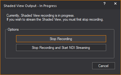
2On the Shaded View Output - In Progress dialog box, click Stop Recording and Start NDI Streaming.
Result: Shaded view recording ends and NDI streaming of the Shaded view begins. The Shaded View Output - In Progress dialog box closes.
Tip: You may click Stop Recording to end the recording only.
To switch from streaming to recording
1During an ongoing NDI Streaming of your Shaded view, right-click and choose Start Video Recording or use CTRL+SPACEBAR.
Result: The Shaded View Output - In Progress dialog box appears.
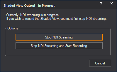
2On the Shaded View Output - In Progress dialog box, click Stop NDI Streaming and Start Recording.
Result: NDI Streaming of your Shaded view ends and Shaded view recording begins. The Shaded View Output - In Progress dialog box closes.
Tip: You may click Stop NDI Streaming to end the streaming only.