Design mode
DESIGN mode was created to provide lighting designers with an avenue for experimentation. Use it as a troubleshooting tool or as a creative tool to help you come up with cue concepts. In DESIGN mode, you can create static lighting looks using the design tools, and then save and render those looks to output photo realistic pictures.
In this section
Beneath the work area in each mode is a series of Layout tabs. These layouts provide various configurations of the views you are working with. To change layouts, click the tab that corresponds to the layout you wish to use.
The DESIGN mode contains the following Layout tabs:
nWireframe: The work area displays a full-screen wireframe view.
nQuad: The work area is divided into quadrants, three of which can be modified to show plan, front, side, or isometric views. The lower-right quadrant contains a Shaded view.
nShaded: The work area displays a full-screen Shaded view.
nCustom: A custom layout, with views defined by the user. See “Custom tab window layout”.
Notes:
nThe wireframe views in DATA mode are used for fixture selection only. To make any drawing modifications, you must return to CAD mode.
nYou can change the properties of the fixtures in DESIGN mode by double-clicking on the fixture, which opens its Properties window.
The design tools are available in the DESIGN and LIVE modes. You must have your venue, scenery and fixtures drawn in order to use the design tools; however, you do not need to have all the data entered for the fixtures in DESIGN mode. DESIGN mode is intended so you do not need channel numbers or a patch. The design tools allow you to create virtual lighting looks without an external control console. You can rough-in static looks and render them for design presentations.
Though the DESIGN mode looks a lot like the CAD mode, you cannot draw anything within the DESIGN mode. If you need to make changes to your drawing, you need to switch over to the CAD mode.
You can change the properties of the fixtures in DESIGN mode by double-clicking on the fixture, which opens its Properties window.
You can see the output of fixtures in the Wireframe and Shaded views within the DESIGN mode. However, you can only select fixtures within the Wireframe views, unless you use Concept shortcuts as discussed in the next section.
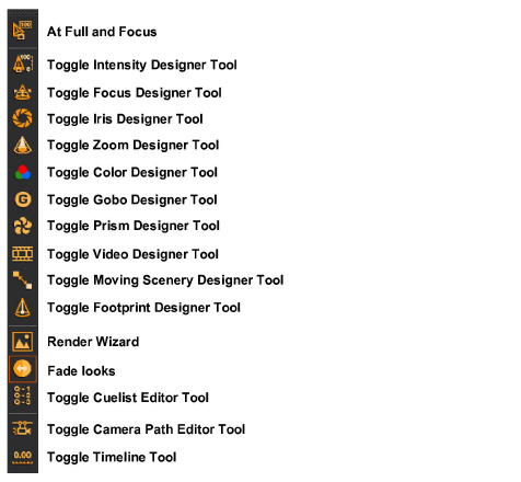
The design tools are individual toolbars that enable you to control certain parameters for selected fixtures. Currently there are ten design tools:
nIntensity
nFocus
nIris
nColor
nGobo
nPrism
nVideo
nMoving Scenery
nFootprint
1From the Design menu, choose the tool name to activate or deactivate the desired design tool.
2You can also toggle the tools on the Design toolbar.
Note: Design tools have the same properties as other toolbars and can be rearranged on the screen to improve the layout of the working area. You can also resize design tools by stacking them into columns so that they take up less space on the screen.
To rearrange and resize design tools
1Open the desired design tools using the steps above.
2Click and drag one tool on top of another. When you release the mouse, the selected design tool lines up under the other.
3Repeat step 2 for as many tools as will fit in a column.
4If you overlay tools so that they are not completely visible, click on the triangle in the tools title bar. This expands or contracts the tool’s window.
5If you click and drag a tool’s title bar off the column, it expands into its own window.
Begin by selecting the desired fixtures.
To select fixtures
Select a fixture (or fixtures). You can select multiple fixtures by holding the CTRL key while clicking on the fixture symbols. You can also use fixture groups as described in “Fixture groups”.
Tip: You can also right-click and drag a box around a section of your drawing to select fixtures. This displays a context-sensitive menu displaying all the fixture types contained within that box. You can then easily select “All Mac500,” for example.
Result: The selected fixtures are highlighted in green.
To invert fixture selection
Press CTRL+SHIFT+I to deselect all the currently selected fixture(s), and consequently select all the other fixtures previously not selected in DESIGN and LIVE modes.
Press CTRL+I to apply invert selection to fixtures, screens and LED walls in DESIGN and LIVE modes.
To use the Intensity tool
The Intensity tool provides many options for setting intensity levels.
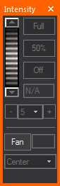
Click the buttons for the extreme settings of intensity: Full (100%) and Off (0%).
You can quickly adjust the intensity by using the Plus or Minus buttons to alter intensity by 5%, 10% or 25%.
Use the dial to achieve any of the settings in between. To use the dial, click and hold the dial while you move the mouse up or down. The chosen intensity level is displayed in the intensity box as you move the mouse. Use the up/down arrows located above and below the dial to change the value by one.
Alternatively, you can enter a specific percentage by typing the number in the intensity box, and then pressing ENTER. The beams will update instantly.
If multiple fixtures are selected, the intensity level entered is assigned to all fixtures. If you select multiple fixtures that have varying intensity levels, “N/A” appears in the intensity box.
The Fan feature enables you to select a group of fixtures, adjust the intensity as a group, and then spread the intensity out with a simple wheel. The fan allows for the distribution of intensity in the following configurations: Center, Left to Right, Right to Left, Chevron In, Chevron Out. Click the Fan button to set the wheel in Fanning mode (color changes), and then move the wheel up or down to change fanning spread of the selected fixtures.
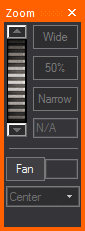
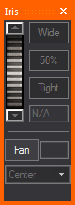
To use the Zoom and Iris tools
The Zoom and Iris tools both work the same way.
Use the buttons for the extreme settings of tight or wide.
Use the dial to achieve any of the settings in between. To use the dial, click and hold the dial while you move the mouse up or down. The chosen value is displayed in the box as you move the mouse. Use the up/down arrows located above and below the dial to change the value by one.
Alternatively, you can enter a specific percentage by typing the number in the zoom or iris box, and then pressing ENTER. The beam will update instantly.
The Fan feature enables you to select a group of fixtures, adjust the zoom or iris as a group, and then spread the zoom/iris out with a simple wheel. The fan allows for the distribution of zoom/iris settings in the following configurations: Center, Left to Right, Right to Left, Chevron In, Chevron Out. Click the Fan button to set the wheel in Fanning mode (color changes), and then move the wheel up or down to change fanning spread of the selected fixtures.
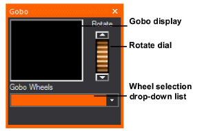
To use the Gobo and Prism tools
The Gobo and Prism tools work the same way. Specify the fixture type (if you have more than one selected), or the specific wheel to control (if that fixture type has multiple wheels) using the drop-down menu. Note that only fixtures with gobo or prism parameters appear on the list. Use the gobo/prism wheel scroll arrows to select the desired gobo/prism from the wheel. If no gobo/prism is desired, leave the wheel in the open slot.The dial will rotate this gobo if a rotating gobo is selected.
The Color tool offers many options for color selection.
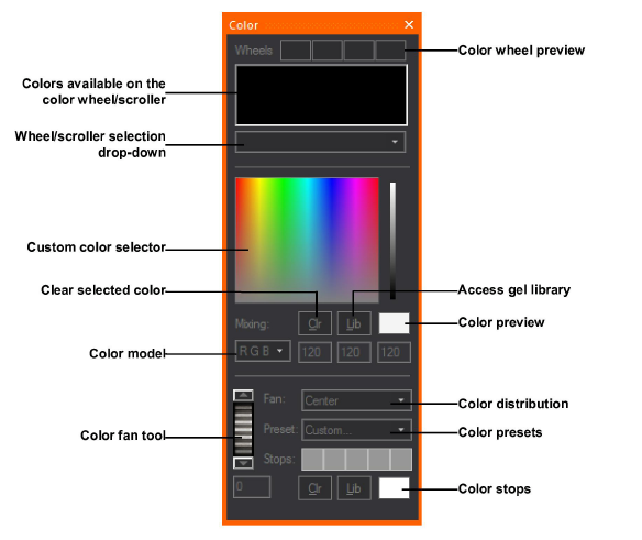
Click the custom color box or use the greyscale arrow to adjust your selection. The Color model values update automatically. The fixture's output depends on its capabilities. If the fixture has CMY or color mixing capabilities, the output is the exact color you selected. If the fixture is only equipped with a color wheel or a non-mixing scroller, the fixture will output the closest color to that selected, based on the available colors on the wheel.
The same principle works if you select a color from the library by clicking the Library button. The wheel/scroller selection drop-down list is as discussed for the gobo wheel. All of the available colors are displayed in the order in which they appear on the wheel or scroll.
To facilitate designing with various fixtures using different color mixing techniques, the Color tool also offers a drop-down list with three different color space models (RGB, CMY, HSI). If you know the RGB values of the desired color, you can enter them, and the custom color box will update. Or if you have the RGB value and want to convert it to the CMY equivalent, change the Color Mixing selection.
You can also preview the color selected at all times using the Color preview box. Double-clicking on the Color Preview box has the same functionality as double-clicking on the Color Picker area, but without affecting your position on the area.
Note: These are valid value ranges for the color spaces:
RGB Color Space: R (0-255), G (0-255), B (0-255)
CMY Color Space: C (0-100), M (0-100), Y (0-100)
HSI Color Space: H (0-360), S (0-100), I (0-100)
The Color Fan feature enables you to select a group of fixtures, adjust the color as a group, and then spread the color out with a simple wheel. The fan allows for the distribution of color in the following arrangements: Center, Left to Right, Right to Left, Chevron In, Chevron Out.
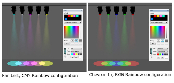
Color Fan offers predefined Color Presets with defined color stops, or custom color stops can be created (limit 5 color stops) using colors chosen from the color selector or gel library.
The focus tool works with fixtures that have variable pan and tilt parameters (i.e., automated fixtures). You must focus conventional fixtures in CAD mode.
Much like on a console, you can lock out Pan and/or Tilt from the Focus tool trackpad in order to prevent movement along a specific axis and help you focus your fixtures more effectively.
The Focus tool gives you the option of using it in either Box or Wheel mode, as shown below:
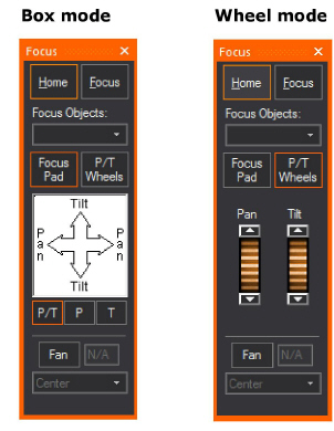
From the Pan and Tilt drop-down list, choose whether you want to lock out either the Pan or Tilt direction. When you do so, you cannot move the fixture beams along the locked out axis. For example, if you select Pan Only, you cannot focus your fixtures along the Tilt axis. To enable focusing in all directions, leave the default Pan and Tilt selected.
Note: This setting applies only to the trackpad itself, and will not prevent you from clicking-and-dragging the beam in a Wireframe view or assigning a Focus Position.
In the focus trackpad, click, hold, and drag the mouse to control the position of the light beam. The Home button resets the fixture to pan = 50% and tilt = 50%.
To send the fixture's beam to a specific location, click the Focus button, and then click in your wireframe drawing. Use the focus position drop-down list to focus the beams of light toward one of the Focus Positions that you created in CAD mode.
You can also use the Focus tool to assign automated fixtures to focus objects that you have drawn in CAD mode. For more information on focus objects, see “Focusing fixtures”.
Note: The Focus tool does not take into account the current viewing position or fixture settings. In one orientation, dragging to the right on the trackpad results in the beam moving left, but rotating the fixture 180 degrees and dragging to the right will cause the beam to move to the right. This effect occurs with both moving mirror and moving head fixtures.
The Fan feature enables you to select a group of fixtures, adjust their focus as a group, and then spread the pan/tilt out with a simple wheel. The fan allows for the distribution of pan/tilt settings in the following configurations: Center, Left to Right, Right to Left, Chevron In, Chevron Out.
Click the Fan button to set the wheel in Fanning mode (color changes), and then move the wheel up or down to change fanning spread of the selected fixtures.
Instead of using the Focus tool, you can also focus fixtures by clicking on the beam in CAD mode Wireframe views and dragging the beam to the desired location.
To focus fixtures with click and drag
1On the CAD Options toolbar, ensure that Toggle Beam Dragging is enabled.
2Turn the fixture on.
3Click on the fixture’s beam and drag it to the desired location.
To assign automated fixtures to focus objects
1In CAD mode, draw a Focus line by choosing Draw > Focus <object>.
Note: Any focus object can be drawn and have fixtures assigned.
2In DESIGN mode, select the automated fixtures in the order in which you would like them to focus.
3On the Focus tool, from the Focus Objects drop-down list, select your focus object.
Streaming video enables you to bring a live or pre-recorded video stream into WYSIWYG and play it back while you set looks in DESIGN mode and while you precue in LIVE mode.
Notes:
nThe Video tool is also available in LIVE mode.
nYou can only incorporate live video if you have WYSIWYG Perform; you cannot select a video from a live capture device or CITP/MSEX stream if you have WYSIWYG Design.
After you draw the screen and attach the video source or subsource or I-Mag camera to it (or to a 3D primitive, an LED Wall, or to a projector that you have inserted from the Fixtures library), you can use the Video Designer tool in DESIGN mode to start the playback or stream. You can view the video in any of the Shaded views, using the controls on the Video Designer tool to pause, fast forward, rewind, or stop the video.
Once you have the video source or subsource or I-Mag camera attached to an object, you must use the Video tool to control it. For more information, see “To draw a screen”, “To configure a new video source for streaming video”, and “To create a new video source in the Video Manager”, and “To create an I-Mag camera in the Video Manager”.
Note: If the video control is patched and DMX connected in LIVE mode, then you will not be able to control the video or video subsource using any of the Video tool commands in DESIGN mode. video sources and subsources can only be controlled by a Designer tool when the DMX source is disconnected; therefore, you must first disconnect the applicable console device from within LIVE mode before using any of the Video tool commands.
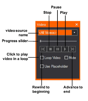
1Click the Shaded tab to view the video screen(s) (or LED Walls or projectors) that you have drawn.
2Click the Toggle Video Designer Tool icon to open the tool window.
3From the drop-down list, select the video source or subsource.
4Use the controls shown in the graphic above to play, pause, or stop the video. You can also use the slider to manually advance or rewind the video at your desired speed.
Note: When you click the Pause button, the frame of the video that is playing at the time is held on the video screen; when you click the Stop button, the video stops playing and the screen goes blank.
Using the Footprint tool, you can change a footprint's focus distance for automated fixtures in the Shaded view of DESIGN mode, in effect making the focus of the footprint "hard" or "soft".
Note: In this release of WYSIWYG, this feature is available in CAD and DESIGN modes only: Footprint Focus is configurable for conventional fixtures in CAD mode and configurable for automated fixtures in DESIGN mode (see “To focus a footprint for a conventional fixture”). Once configured, all fixtures can be visualized in DESIGN mode. In an upcoming release, the Footprint Focus feature will be extended to function in LIVE mode like all other Designer tools.
1Select the automated fixture and open the Footprint tool.
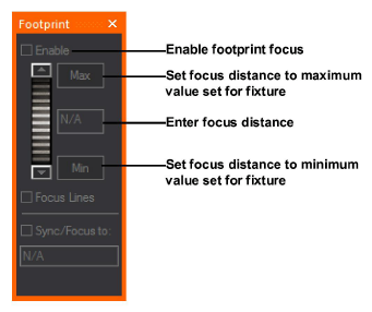
2Check Enable to enable Footprint Focus for the selected fixture(s).
3Adjust the focus distance using the slider or by entering a value in the Focus Distance box. Click the Min and Max buttons to set the value to the fixture’s minimum or maximum focus distance, which are defined on the General tab of the fixture’s Property page in the Footprint Settings section.
4Check Focus Lines to display focus lines for the selected fixture(s) in Shaded view.
5Check Sync to Focus Position to adjust the footprint focus distance to the specified Focus Position.
The effect is visible in the Shaded view when Footprint Focus is enabled on the Simulation tab of the View Options window.
After drawing motion axes or frames and attaching objects to them, you can use the Moving Scenery Designer tool to make the object “move” along each axis.
You can simulate moving scenery by setting up looks containing motion axes or frames in DESIGN mode. Once you create the look and specify its fade time, use the Moving Scenery Designer tool to customize the look by selecting the appropriate motion axis or frame and the object’s starting position on it. Then create a second look, repeating the same procedure to set the object’s starting position on either the same axis or frame, or a different one (if there is more than one axis attached together).
When you switch from one look to the next, you can see the object move from the starting point of the first look, to the starting point of the second look within the time period that you define as the “fade time”.
To use the Moving Scenery tool
After drawing motion axes/frames and attaching objects to them, you can use the Scenery tool to make the object “move” along each axis.
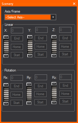
1In DESIGN mode, click the Toggle Moving Scenery Designer Tool icon to open the tool.
Note: You can also open the tool by clicking Design > Moving Scenery tool.
2From the drop-down list, select the appropriate motion axis or frame.
3If you selected a linear axis, the X scroller is enabled. If you selected a rotational axis, the Rx scroller is enabled. If you selected a motion frame, all scrollers with activated motion ranges are enabled.
4To move the object on the axis, you have four choices:
nUse the scroller to move the object back and forth along the axis.
nClick Start or End to move the object immediately to either the start or end of the motion axis.
nClick the Home button to move the object to its original position.
nFor very precise positioning, in the box provided, type the object’s position as a percentage of its total range of movement and press ENTER. For example, if you want to see the object at the exact half-way mark, type 50 in this box, and then press ENTER.
In Shaded view, Highlight sets the currently selected fixture(s) to an open beam at 100% full intensity temporarily, without changes to the fixture’s saved settings.
Highlight can be accessed from the Design menu or the Fixture Selection toolbar.
Highlight is useful when identifying a single fixture or a small selection of fixtures within a large and complex plot.
To use the Highlight tool
1From the Design menu, choose Highlight.
Tip: You may also use the Highlight tool on the Fixture Selection toolbar or use the hotkey H on your keyboard.
|
|
The Highlight button. |
2In Shaded view, select a fixture or multiple fixtures.
Result: The selected fixture(s) is highlighted showing an open beam at full intensity.
3Click on the next fixture that you wish to highlight.
Result: The next fixture selected is highlighted showing an open beam at full intensity, and the previously highlighted fixture goes back to its previous state.
Note: The displays in the Design tools windows associated with the highlighted fixture(s) will appear in white/clear.
This feature offers the ability to display the intensity level applied to a fixture and appears as a Fixture Attribute. The intensity level value is displayed as part of the Fixture Symbol text in the wireframe views in CAD, DESIGN, and LIVE modes; and in Layouts in the PRES mode.
To use update intensity labels tool
1From the Options menu in CAD mode, choose Document Options.
2In the Document Options window, click Fixture Attribute Details.
3Select the Intensity checkbox under the Show on Plot column.
4Click OK.
Result: The Update Intensity Labels tool is enabled and the current intensity value applied to a fixture is displayed as part of the Fixture Symbol text.
5From the Design menu in DESIGN mode, click Update Intensity Labels.
Result: The intensity value displayed in Layouts (PRES mode) and Wireframe views is updated according to the current intensity level applied to the fixture.
6From the Live menu in LIVE mode, click Update Intensity Labels.
Result: The intensity value displayed in Layouts (PRES mode) and Wireframe views is updated according to the current intensity level applied to the fixture.
Fixture groups are custom groups of fixtures. You can create fixture groups in CAD, DATA, DESIGN, or LIVE mode in any view that allows fixture selection.
Creating a fixture group allows you to select a group of fixtures at the same time.
Fixture group shortcuts also enhance working with design tools in Shaded view. Since design tools work with the current fixture selection, opening multiple fixture group shortcuts allow you to change different groups of fixtures, rather than having to select them individually in the Wireframe view.
Notes:
nFixture groups are saved on the Fixture Group shortcut bar.
nIf ONLY fixtures are selected, either CTRL+G or CTRL+J will create a Fixture Group.
nIf fixtures and more than one other object is selected, CTRL+G will create a normal “Objects Group” from the selected objects (the same if there were no fixtures in the selection), while CTRL+J will create a Fixture Group (the same as if CTRL+G was used with only fixtures selected).
1Select the fixtures that you want to group. If you are unfamiliar with selecting objects, refer to “Selecting”.
2Click the Fixture Groups shortcut bar.
3Right-click the Fixture Groups shortcut bar, and then choose New Fixture Group. Alternately, you can click the new fixture icon.
4Type the name of the fixture group, and then click OK.
Result: The fixture group is saved on the Fixture Groups shortcut bar.
You can modify a fixture group shortcut by adding or removing fixtures as required.
To update fixture groups
1Select the set of fixtures that you want to include in the fixture group.
2Right-click on the Fixture Groups shortcut that you want to update, and then choose Update.
Result: The Fixture Groups shortcut is modified to include only the fixtures that you selected.
To add fixtures to an existing fixture group
1On the Fixture Groups shortcut bar, click on a Fixture Group to select the fixtures in the group.
2Press and hold CTRL and click on the fixtures that you wish to add to the selected Fixture Group.
3Right-click on the selected Fixture Group on the Fixture Groups shortcut bar.
4Select Update from the pop-up menu.
Result: The selected fixtures will be added to the Fixture Group.
To remove fixtures from an existing fixture group
1On the Fixture Groups shortcut bar, click on a Fixture Group to select the fixtures in the group.
2Press and hold CTRL and click on the fixtures you want to remove from the selected Fixture Group.
3Right-click on the selected Fixture Group on the Fixture Groups shortcut bar.
4Select Update from the pop-up menu.
Result: The selected fixtures will be removed from the Fixture Group.
When you select a Fixture Groups shortcut, any currently selected objects are deselected, and the fixture group set is selected instead.
If you press the CTRL key while selecting fixture groups, the fixture group is added to the current selection set.
If you press the CTRL and SHIFT keys while selecting fixture groups, the fixture group is removed from the current selection set.
Tip: Fixture groups can be used to select fixtures even while in Shaded view.
Notes:
nIn a fixture group shortcut, multi-cell fixtures, such as cyc lights, can be selected either by cell or fixture. If the fixture group was created in DESIGN mode using cells, the entire fixture is selected in the other modes. If the fixture group was created using fixtures, all cells are selected when in DESIGN mode.
nWhen you replace a multi-cell fixture that is selected by circuit with a different multi-cell fixture that has a different number of circuits, the replacement fixture is selected by fixture and not by circuit.
nWhen you delete a fixture, the fixture is removed from all fixture groups that include that fixture.
nWhen you replace a fixture using the Replace Fixtures menu option, any fixture groups referring to that fixture are updated to refer to the fixture replacement.
nAny fixture added to a document will not initially be part of any fixture group.
You can create palettes of color to facilitate color selection. A palette is a reference to a specific color and can be used on all color-changing fixtures and scrollers.
Creating a Palette shortcut is helpful if you want to save your favourite CMY color mixes for later use.
Note: You can create palettes in DESIGN mode only.
1Select the fixture from which you want to capture the color.
Note: You can create a palette from only one fixture.
2Right-click on the Palettes shortcut bar, and then choose New Palette.
3Type the name of the palette, and then click OK.
Result: The CMY value is saved as a palette on the Palettes shortcut bar. This value can be a CMY mix, a color from the color wheel or scroll, or a combination of color sources.
You can modify a Palette shortcut by modifying or replacing colors as required.
To update a palette
1Select the fixtures from which you would like to record the palette.
2Right-click on the Palettes shortcut that you want to modify, and then choose Update.
Result: The Palette shortcut is updated with the new CMY values.
To apply a palette
Applying a color palette is the equivalent of setting up color parameters for the selected fixtures, except it is much faster.
1Select the fixtures for which you want to assign the specific color value.
2Click on the desired palette shortcut.
Result: The fixtures are assigned the recorded copy value. If the fixture has CMY or color mixing capabilities, the output is the exact color that you selected. If the fixture is only equipped with a color wheel or a non-mixing scroller, the fixture outputs the closest color to that selected, based on the available colors on the wheel.
Changes that you make with the design tools update the currently selected look. The name of the currently selected look is displayed at the top of the working area. Before making changes, always check that the currently selected look is the one that you want to modify.
1In the shortcuts bar, click Looks.
2In the Looks shortcut area, right-click, and then select New Look.
3In the Name box, type the name of the new look.
4In the Fade time box, type the fade time in seconds for this look. This is the amount of time that it takes to “fade” to this look when you click on it from another look on the shortcut bar. For more information, see “Cross-fading between lighting looks” below.
5Click OK.
6Scroll to the bottom of the Looks shortcuts list.
7Click on the shortcut for your new look.
8Use the design tools to create your new lighting look.
Tip: To build on an existing look without losing it, clone the look shortcut and work from the copy of the shortcut. For more information on cloning shortcuts, see “To clone a shortcut”.
Cross-fading between lighting looks
You can use the Looks shortcut bar to quickly set up and run timed transitions between lighting looks without the need of a lighting console. When you create a lighting look, you can specify its fade time in seconds. This is the amount of time that it takes to “fade” to this look when you click on it from another look on the shortcut bar. You can create multiple looks and specify different fade times for each of them.
Once you create the look and specify the fade time, you can use the design tools to customize the look. For example, you can add color, gobos, and intensity to lighting, and set the position of moving lights. When you switch from one look to the next, you can see the movement of the lights from one position to the next, along with any changes you have made between looks, such as color, intensity, and so on.
To cross-fade between looks
1In DESIGN mode, in the shortcuts bar, click Looks.
2In the Looks shortcut area, right-click, and then select New Look.
3In the Name box, type the name of the new look.
4In the Fade time box, type the fade time in seconds for this look.
5Click OK.
6Scroll to the bottom of the Looks shortcuts list.
7Click on the shortcut for your new look.
8Use the design tools to create your new lighting look. You can set the color, intensity, zoom, iris, and add gobos. If you are using moving lights, you can also set the position of the lights.
9To create the next look, in the Looks shortcut area, right-click, and then select New Look.
10In the Name box, type the name of the new look.
11In the Fade time box, type the fade time in seconds for this look.
12Click OK.
13Scroll to the bottom of the Looks shortcuts list.
14Click on the shortcut for your new look.
15Use the design tools to create your new lighting look. You can set the color, intensity, zoom, iris, and add gobos. If you are using moving lights, you can also set the position of the lights.
16Ensure that the Fade Looks menu is enabled so the look fades instead of jumping directly to the next look.
Tip: If the button is not enabled, then you can “jump” from one look to the next by clicking the look shortcuts on the shortcut bar. Even if the button is enabled, you can always jump to the next look by right-clicking the look shortcut, and selecting Jump to.
17To watch the “fade” from the first look to the second look, click the shortcut for the second look. The image fades over the period of time that you specified for the second look.
Tips:
nFor a more realistic view of the fading between looks, click the Shaded tab.
nWhen cross-fading between Looks, a simple countdown (of the remaining fade time) will be displayed in Shaded view.
nTo jump directly to a specific look, right-click the look, and then select Jump to.
You can use the Looks shortcut bar to quickly set up and run timed transitions between looks to simulate moving scenery.
When you create a look, you can specify its fade time in seconds. This is the amount of time that it takes to “fade” to this look when you click on it from another look on the shortcut bar. You can create multiple looks and specify different fade times for each of them.
Just as you can specify the fade time to watch the transition between lighting looks, so too can you use the fade time to simulate moving scenery. In the latter case, however, your Look must contain at least one motion axis with at least one object attached to it.
Note: You can also combine Looks to simulate both moving lights and moving scenery in one “fade”.
Once you create the look and specify its fade time, use the Moving Scenery Designer tool to customize the look by selecting the appropriate motion axis and the object’s starting position on it. Then create a second look, repeating the same procedure to set the object’s starting position on either the same axis, or a different one (if there is more than one axis attached together).
When you switch from one look to the next, you can see the object move from the starting point of the first look, to the starting point of the second look.
Note: Before you perform this procedure, you must have drawn at least one motion axis and attached at least one object to it. For details, see “Drawing motion axes”.
1In DESIGN mode, in the shortcuts bar, click Looks.
2In the Looks shortcut area, right-click, and then select New Look.
3In the Name box, type the name of the new look.
4In the Fade time box, type the fade time in seconds for this look.
5Click OK.
6Scroll to the bottom of the Looks shortcuts list.
7Click on the shortcut for your new look.
8Click the Toggle Moving Scenery Designer Tool icon.
9From the drop-down list in the Scenery window, select the appropriate motion axis.
10Click the slider to advance the object to the position where you want it to start on the selected axis.
Note: You can also use the Start box to type the object’s position as a percentage of its full range of movement. For example, to show the object at the exact half-way mark on the motion axis, type 50.
11To create the next look, in the Looks shortcut area, right-click, and then select New Look.
12In the Name box, type the name of the new look.
13In the Fade time box, type the fade time in seconds for this look.
14Click OK.
15Scroll to the bottom of the Looks shortcuts list.
16Click on the shortcut for your new look.
17From the drop-down list in the Scenery window, select the appropriate motion axis.
18Click the slider to advance the object to the position where you want it to start on the selected axis.
19Ensure that the Fade Looks menu is enabled so the look fades instead of jumping directly to the next look.
Tip: If the button is not enabled, then you can “jump” from one look to the next by clicking the look shortcuts on the shortcut bar. Even if the button is enabled, you can always jump to the next look by right-clicking the look shortcut, and selecting Jump to.
20To watch the “fade” from the first look to the second look, click the shortcut for the second look. The object moves from the starting point of the first look to the starting point of the second look over the period of time that you specified as the fade time for the second look.
Tips:
nFor a more realistic view of the fading between looks, click the Shaded tab.
nTo jump directly to a specific look, right-click the look, and then select Jump to.
nFor details on controlling the object’s movement with a console device, such as the Mini Console, see “To control a DMX patched motion axis with a console”.
Cuelists enable you to play back stored Looks in any order, without having to resort to the crossfade function described in the previous section.
To create a cuelist
1On the Design toolbar, click the Toggle Cuelist Editor Tool icon.
Result: The Cuelist Editor window appears.
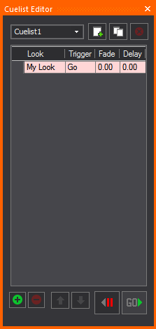
2In the top-right corner of the tool, click the Create a new Cuelist button.
3Type a name for the Cuelist, and then click OK.
To rename a cuelist
1In the Cuelist Editor tool, click the drop-down list on the top left corner and select the Cuelist that you want to rename.
2With the Cuelist highlighted, type the new name, and then press ENTER.
To copy a cuelist
This procedure is useful when you set up one Cuelist with Looks in a certain order, but want to see how the same Looks would "play out" in a different order.
1Click to select the Cuelist that you want to copy.
2Click the Clone current Cuelist button in the top right corner.
To delete a cuelist
1Click to select the Cuelist that you want to delete.
2Click the Delete current Cuelist button in the top right corner.
To add a cue to the cuelist
1To add a cue to a Cuelist, select the Cuelist from the drop-down list on the top left corner.
2Click the + button (lower right corner) to add a cue.
Note: To delete a cue, select it and then click the minus (- ) button in the bottom right corner.
To adjust the position of a cue
To adjust the position of a cue in the list, click to select it, and then move it up and down using the arrow buttons in the lower left corner.
To add a look to a cuelist
Once you add a cue, you can assign a Look to it by clicking the drop-down list in the Look column and selecting the appropriate Look.
Setting cue triggers
There are two types of triggers that you can set for each cue in your Cuelists:
nGo: The fade for the current cue will start immediately (the delay time is 0 seconds).
nFollow: The fade for the current cue will activate automatically after the set delay time has passed.
To switch between triggers, click to select the appropriate cue, and then click in the Trigger cell. From the drop-down list, you can toggle between Go and Follow.
Setting the fade time
The fade is the time (in seconds) that it takes to transition between the previous cue and the current cue.
Notes:
nThe fade time is in no way related to the crossfade time set for individual looks.
nThe fade always starts after the delay time has passed.
To enter the fade time, click to select the appropriate cue, and then click in the Fade cell to type the new fade time.
Setting the delay time
The delay is the time (in seconds) that it takes for lights to start fading into the current cue. To enter the delay time, click to select the appropriate cue, and then click in the Delay cell to type the new delay time.
To activate a cue
To activate a cue, hit the Go button. Note that if the next cue has a 'follow' trigger, it will start as soon as its delay time has passed.
To stop playing a cuelist
To stop playing a Cuelist, click the <|| button. Click the same button to step back through cues, disregarding fades and delays.
Tips: To "jump into" a cue (i.e., ignoring fade and delay times), double-click in the grey area to the left of the cue. You can use the arrow keys to navigate the Cuelist table.
Once you draw a Camera Path in CAD Mode, you can use the Camera Path Editor and the Timeline tool in DESIGN or LIVE mode to define the time interval between two nodes along the path. If there are Camera Targets inserted in the file, you can also specify when the camera should follow a camera target. Finally, you can also define the orientation and field angle of the Camera at the current node position.
Once you have defined the time intervals and camera’s orientation, you can open the Timeline tool and watch the Camera Path play in Shaded view. Camera Path playback is also simulated in Full Screen mode.
You can also patch a Camera Path to a DMX universe and then control the camera’s movement through a console. For details, see “Patching camera paths”.
Once you create a Camera Path in CAD mode, follow the steps in this section to define the time intervals between the nodes on the path, change camera behavior, assign targets to camera nodes, and reposition nodes in space. For details on drawing Camera Paths, see “Drawing camera paths”.
Camera Path Editor window
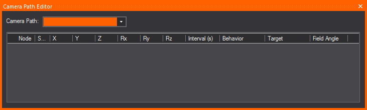
Camera Path Editor columns
nNode: This column gives you the Node number of the nodes on your Timeline.
nShortest Path: When the Shortest Path checkbox is selected for a node, it forces the camera to rotate as little as possible when moving between two nodes on your timeline. When the Shortest Path checkbox is cleared for a node, the camera will take the longer of the two directions as it rotates to aim at the next node's target. This applies to Roll, Pitch and Yaw.
nX, Y, and Z Columns: The X, Y, and Z columns in the Camera Path Editor are editable position information for each of the nodes on your timeline. You may enter in distance values into these fields to re-position your nodes as you see fit.
nRx, Ry, and Rz Columns: These columns represent the rotation around each of the X, Y, and Z axes in WYSIWYG. These columns are non-editable, but allow you to get positional information from your nodes.
n Rx, or Rotation around the X Axis = PITCH [tilting forward and backward]
nRy, or Rotation around the Y Axis = ROLL [tilting side to side]
n Rz, or Rotation around the Z Axis = YAW [also called Heading or Direction]
nInterval: A node’s Interval is how long it takes in seconds to get from one node to another. For example, if the timing on node 2 is ten seconds (10s), then the camera would move for ten seconds before reaching node 2.
nBehavior: Behavior is the camera’s movement and direction behavior as it relates to the Camera Path. There are three types of Camera Behavior:
nFollow Path: The camera will follow straight along the path, not deviating in any way possible from the path as it travels between nodes.
nFollow Target: The camera will always point at an assigned Camera Target if this behavior is chosen for a node.
nUser Defined: This option allows the camera to behave exactly as specified by a user, meaning that the camera will point wherever you point it when the User Defined behavior is chosen.
nTarget: Each node can be assigned a different target when the Follow Target behavior in the Behavior column is chosen. The Target column is a drop-down list for choosing different targets in your drawing.
nField Angle: This option allows you to enter in different field angles for each node.
1In Wireframe view, from the Design menu, choose Camera Path Editor.
2In the Camera Path Editor, from the Camera Path drop-down list, select the Camera Path that you want to edit.
3In the Interval column, adjust the timing for each node along the path, specifying when you want the camera to be at that node.
nIf you have placed targets along the path, and you want the Camera to follow a target at a particular node, in the Target column click in the cell corresponding to the node and, from the drop-down list that appears, select Follow Target. Then, click in the adjacent Target cell to select the target.
nTo define the orientation and field angle of the Camera at a particular node along the path, in the Camera Target column, click in the cell corresponding the node, and then select User Defined.
4Once you have defined the time intervals, you can use the Timeline tool to watch the Camera Path play in the Shaded view. For details, see below.
Visual Camera Path Builder tool
The Visual Camera Path Builder tool allows you to create a Camera Path on the fly while you move the Camera around your space. This tool essentially works by placing a node at the Camera’s current position once you’ve told WYSIWYG that you are satisfied with the Camera’s current placement on screen.
Note: The Visual Camera Path Builder tool is disabled if the Shaded View Camera Control was set to Other 3D Applications in the General tab of the Application Options window.
To use the Visual Camera Path Builder tool
1Right-click in the Shaded view and select Visual Camera Path Builder.
2Once you’ve started the Visual Camera Path Builder, you’ll be prompted to name your new path, add it to the Camera layer (or a layer of your choosing), and create the first node based on the Camera’s current position.
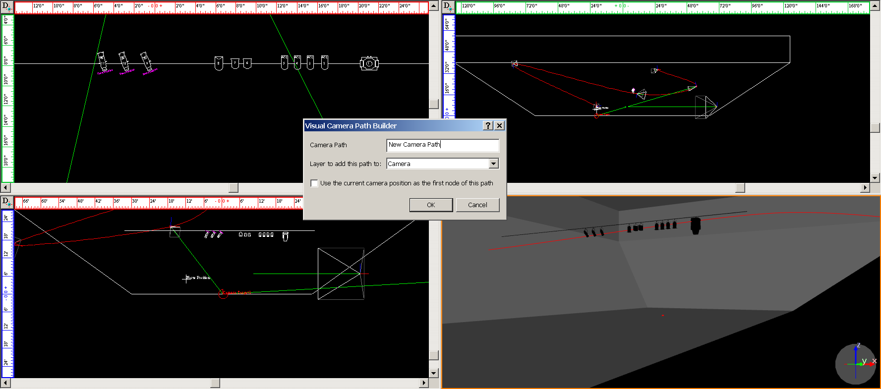
3Once you click OK in the dialog box, you will then be in Visual Camera Path Editor mode. Maneuver the Camera around the space, and when you want to create a new node based on your Camera’s position, right-click in the Shaded view and choose the Add Node. At this point, you can also Abort your Camera Path in the Visual Camera Path Builder tool.
4Move the Camera and right-click every time you would like to create a new node from your Camera’s current position in space.
5When you have created as many nodes as you would like to have in your Camera Path, right-click again in the Shaded view and choose Finish Camera Path.
6At this point, you can also Abort your Camera Path, or you can choose to Close the Camera Path from your current view, which will create a seamless loop on the Camera Path. When you are finished with the Visual Camera Path Builder tool, you will automatically exit the Visual Camera Path Builder tool mode.
Once you have adjusted the timing of a Camera Path with the Camera Path Editor, switch to the Shaded view to watch the camera move along the path with the Timeline tool. This tool enables you to watch the timing in slow motion, regular speed, or up to four times the speed.
Notes:
nCamera Path playback is also simulated in Full Screen mode.
nNodes of existing Camera Paths can be edited from a Shaded view when the Timeline's Previous Node or Next Node buttons are used; they can only be edited while playback is paused.
1In Shaded view, click View > Timeline.
Result: The Timeline tool appears.
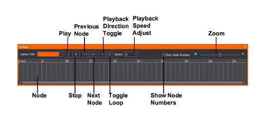
2Use the controls to watch the Camera move along the path you have defined:
nPlay: Click to start the Camera Path simulation in the Shaded view. While this plays, the red line moves along the timeline to display its current position. You can click on the red line indicator and scrub along the timeline, which updates the red line and the Camera simulation at the corresponding point along the path.
nStop: Click to stop the camera.
nPrevious Node: Click to switch back to the previous node on the path.
nNext Node: Click to move to the next node on the path.
nToggle PlayBack Direction: Click to switch the direction of the camera on the path.
nToggle Loop: Click to keep the camera moving on the path in a continuos loop.
nAdjust Playback Speed: Click to choose the playback speed.
nShow Node Numbers: Click to show the node numbers in the timeline.
nZoom: Use the slider to zoom in or out on the timeline.
Note: When the DMX Control for Cameras/Camera Paths is enabled in Camera Manager, the controls in the Timeline tool are disabled in LIVE mode, as DMX will be in control of all Camera Path playback and settings.
In WYSIWYG, you can render lighting looks to produce high quality images of your set and lighting. Rendering uses a full range of effects, including depth of field, motion blur, soft shadows, and antialiasing settings to produce a photorealistic image.
Based on the product level that you are running, when you are creating a rendering, you have two choices:
nRender Wizard: (all product levels except Report) You can use the interactive editing and advanced visual effects of the Render Wizard to set up the look that you want to render, and then create the rendering. In this case, you must leave WYSIWYG running while the Render Wizard finishes the image. You have the choice of saving the image to an external folder that you specify or within WYSIWYG on the Images tab.
nBackground Rendering Manager: (all product levels except Report and Perform - Console Edition) You can use the Render Wizard to set up the look that you want to render, and then send the render job to the Background Rendering Manager to create the rendering.
This feature lets you use the Windows taskbar to queue render jobs that will execute in the background without requiring WYSIWYG to run, letting you do other tasks while the Render Engine works independently. You can also pause and resume renderings without losing your render, and shut down/restart your computer without losing your rendering progress. For details on this feature, see “Background Rendering Manager”.
1In the working area of the screen, display the lighting look that you want to render.
2From the Design menu, choose Render.
Tip: You can also click the Render Wizard icon in the Design toolbar.
Result: The Render Wizard appears and guides you through a series of options.
Step 1 - Set Output Destination and Image Size
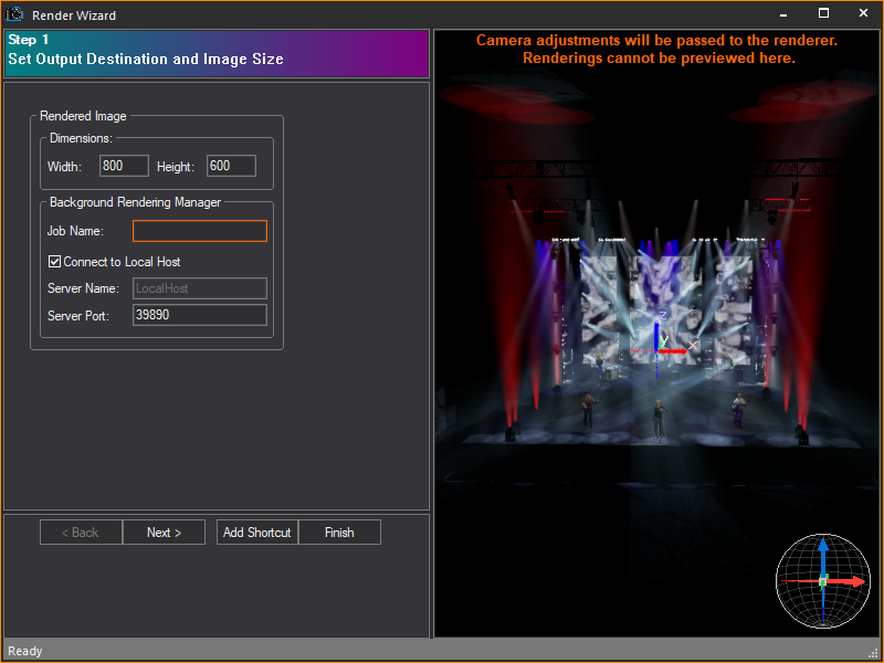
Click in the right pane to arrange the image that you want to render. You can click and drag the image around, zoom in and out with the mouse wheel (or PAGE UP / PAGE DOWN keys), or set up your shot accurately using a camera.
Note:
nMake sure you use the appropriate aspect ratio (height vs. width) for the output device that you will be using to present the pictures. For example, TV is 4x3 (normally 640x480), HDTV is 16x9.
nIf this is the first time you are using the Background Rendering Manager, you must configure it before the rendering process will begin. Upon clicking Finish in the Render Wizard, the Background Rendering Manager Configuration Wizard appears, enabling you to configure settings such as the Network Port, the default folder for storing rendering files, and other Manager settings. For details, see “To configure the Background Rendering Manager”.
a.Dimensions: Type a value in pixels for the width and height of the final image.
b.Job Name: Type a name for the rendering job.
c.Connect to Local Host: Select this checkbox to use the default values and have the Render Wizard send all jobs to the Background Rendering Manager that is running on your computer. To send render jobs to another computer in your network that is running the Background Rendering Manager, clear this checkbox and then type the server name and port number in the boxes provided. Note that when you send render jobs to a network computer, the Background Rendering Manager must be open and running on this destination computer; in this case, the act of sending a job from the Render Wizard does not launch the Background Rendering Manager.
d.Server Name: Type the name of the server in your network that is running the Background Rendering Manager where you want the Render Wizard to send all render jobs. The server must be running WYSIWYG Release 18 (or higher) and have a dongle attached.
e.Server Port: Type the port number that the WYSIWYG Render Wizard will use to send render jobs to the Background Rendering Manager, or accept the default port number shown. It must be a value between 1025 and 65,535. For proper communication, this number must match the port number that is configured in the Background Rendering Manager on the destination computer; therefore, if you change this value, you must also change it in the Background Rendering Manager on the destination computer. For details, see “To configure the Background Rendering Manager”.
Note: By default, the Background Rendering Manager runs on the same system as WYSIWYG. You can also run it on a separate machine. For more information, see “Background Rendering Manager”.
Step 2 - Set Camera and Simulation Type
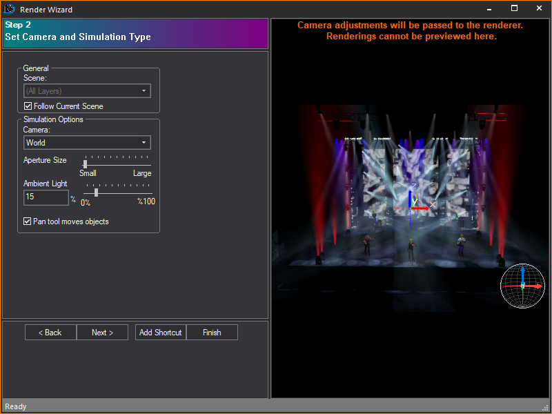
Options in Step 2 affect the composition of your image.
a.Scene: Select a scene for the rendering. Scenes are groupings of layers used to organize a plot. For more information on scenes, see “Scenes”.
b.Follow Current Scene: Select this checkbox to use the scene that is displayed in the Scene drop-down list. Clear the checkbox, and then select the desired scene from the Scene drop-down list.
c.Camera: Select the camera for the rendering. Cameras are set up in CAD mode. For more information on cameras, see “Drawing cameras”.
d.Aperture size: Use the slider to adjust the camera aperture. This adjustment changes the depth of field of the final image. The larger the aperture, the “fuzzier” the rendering. The focus point is always the target of the camera.
Note: By default, the red lines indicating the Camera Target are visible. This is to aid in the composition of the image. It will not, however, be visible in your final rendering. To turn the target off (that is, set to not visible), right-click in the preview pane, and then choose View Options. For more information on Shaded view, see “Modifying shaded views”.
e.Ambient Light: Use the slider or type a value in the box to set the ambient light level. This adjusts the overall light level, where 0% is complete black and 100% is a bright room. This does not affect the intensity of the fixtures in your lighting look.
f.Pan tool moves objects: The Pan tool does not affect the outcome of your rendering. Rather the tool rotates the model on the target (if checked) or rotates the camera around the target (if unchecked). Both settings help you to compose your image.
Step 3 - Add Atmospheric Effects to Your Rendering
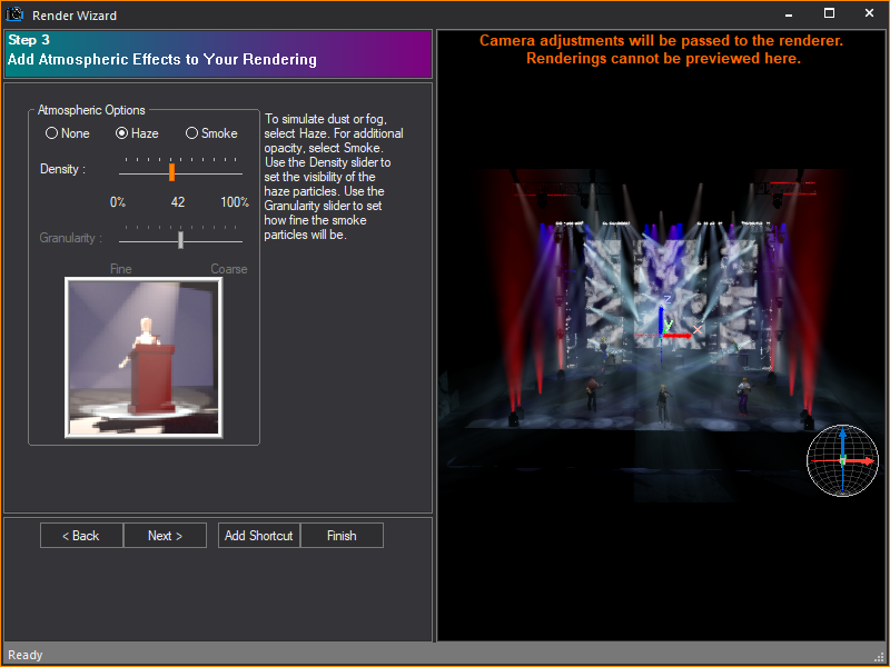
Options in Step 3 affect the atmospheric conditions in your rendering.
a.Atmospheric Options: The options that you set here affect the atmospheric conditions that are visible in your final rendering. To simulate atmospheric dust or fog, select Haze. For additional opacity, select Smoke.
b.Density: Use the slider to set the visibility of the haze particles. A setting of 0% indicates that the particles cannot be seen.
c.Granularity: Use the slider to set the granularity of the smoke. This setting affects how fine smoke particles are. This option is available only if you choose Smoke under Atmospheric Options.
Step 4 - Select How Shadows Will Be Simulated
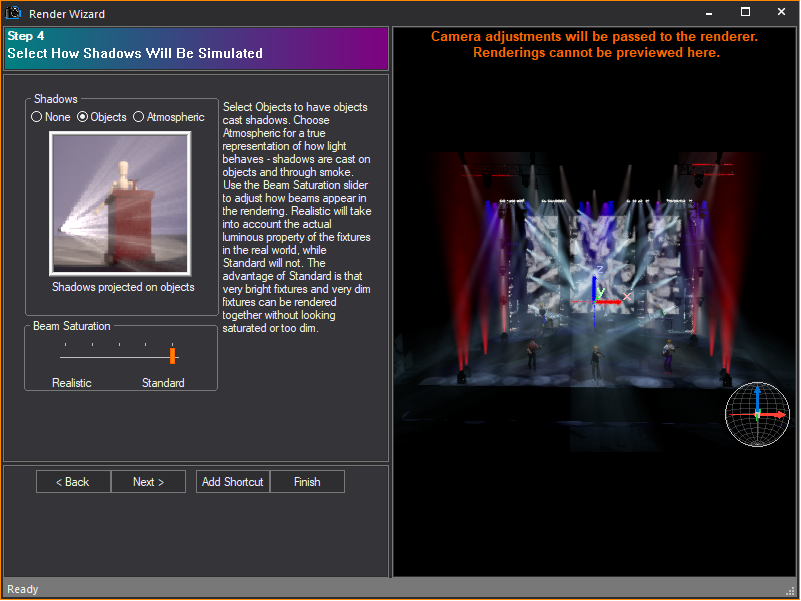
Options in Step 4 affect the projection of shadows in your rendering.
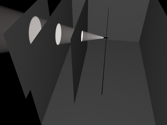
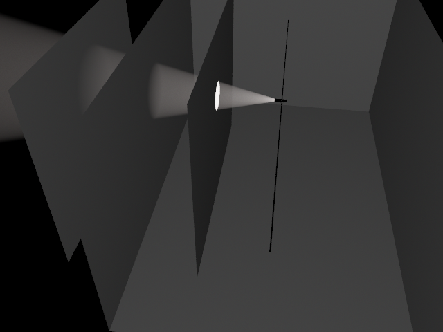
a.Shadows: Select how you want shadows to be projected in the final rendering. If you choose None, then no shadows are calculated by WYSIWYG; that is, objects in the path of the light beam do not create shadows. Instead, all objects in the path of the virtual beam are illuminated, even if an object would normally block the beam from reaching another. As illustrated in the rendering below, all three surfaces are illuminated and the beam continues into infinity.
To calculate which objects the beam of light will hit and which objects it will not hit, select Objects. Objects in the path of the virtual beam will not be illuminated by the beam if the beam has already been blocked by another object. However, WYSIWYG still does not calculate where the beam stops. As illustrated in the rendering below, the first surface is illuminated, but the beam is still continuing into infinity.
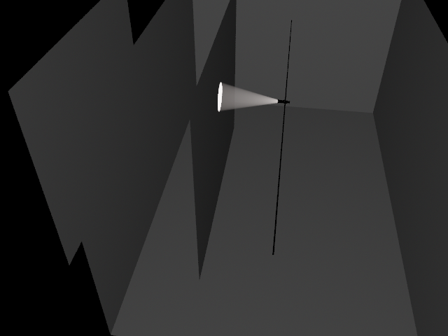
Select Atmospheric to calculate which objects the beam of light will hit and where the beam of light will end. This is a true representation of how light behaves. As illustrated in the rendering below, the first surface is illuminated and the beam also stops there.
b.Beam Saturation: Use the Beam Saturation slider to change the relative brightness of fixture beams. When set to Realistic, WYSIWYG accounts for all variations in lamp output, including gel transmission, color temperature, fixture efficiency, and lamp. When set to Standard, all fixture beams are rendered at the same general intensity.
Step 5 - Define How Light Reflection Will Be Simulated
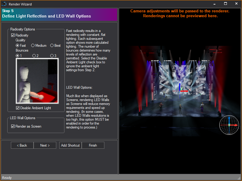
Options in Step 5 affect the radiosity level. Radiosity is defined as the combined processes of emission, transmission, and absorption of rays or reflecting beams of light. When using Radiosity, it is not necessary to use ambient lighting.
a.Radiosity: To generate a rendering that uses radiosity, select the Radiosity checkbox, and then choose from the available radiosity options. Fast radiosity results in a rendering with constant, flat lighting. Each subsequent option shows more calculated lighting. The number of bounces determines how many levels of reflection are permitted.
b.Disable Ambient Light: Select the Disable Ambient Light checkbox to ignore the ambient light settings from Step 1.
c.Render as Screen: Select the Render as Screen checkbox to display the LED wall as a screen with a projected image instead of a detailed grid of LED pixels forming the image. Render as Screen is only available if the source of your LED wall is color, image or video. Render as Screen does not work if the source of the LED wall is Dynamic DMX patch.
Step 6 - Add Environmental or Outdoor Lighting to Your Rendering
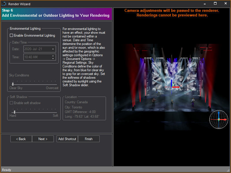
Options in Step 6 affect the presence and quality of environmental or outdoor lighting. Note that for environmental lighting to have an effect, your show must not be contained within a venue.
a.Enable Environmental Lighting: To generate a rendering that considers outdoor lighting conditions, select the Enable Environmental Lighting checkbox.
b.Date and Time: The date and time of the rendering determines the position of the sun and/or moon and the resulting amount of light available. The position of the sun is also determined by the geographic settings that are configured in Document Options and the north direction that is set in CAD mode. For more information on regional settings, see “Regional Settings tab”. For more information on setting the direction that is north, see “Drawing a compass”.
c.Sky Conditions: The amount of light available determines the brightness of the resulting rendering. Use the Sky Conditions slider to adjust the quality of light.
d.Soft Shadow: Select the Enable soft shadow checkbox, and then use the slider to set the softness of shadows that are created by sunlight. The softer the shadow, the less sharp the resulting shadow.
Step 7 - Use Anti-Aliasing to Smooth or Sharpen Rough Edges
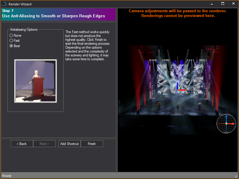
Options in Step 7 affect the antialiasing settings. Antialiasing is a method of smoothing out and sharpening rough or jagged edges of images to produce a more polished result. This method subsamples the pixel area and averages the results of neighboring samples to reduce the areas of high contrast (edges).
a.Antialiasing Options: Choose how you want edges to appear in your final rendering. The Fast method samples the pixels quickly, but does not produce the highest quality.
b.Click Finish to start rendering. The total rendering time depends on the options that you selected and the complexity of the scenery and lighting. Based on the location where you chose to save the completed rendering in Step 1, your options vary upon clicking Finish:
WYSIWYG sends the render job to the Background Rendering Manager, then a status window appears, showing the progress as the render job is sent to the Background Rendering Manager on the destination computer (either your own or another server in the network).
When the job has been sent successfully, you can open the Background Rendering Manager to check its progress. You can close the Render Wizard and WYSIWYG, queue jobs, pause and resume them, and shut down/restart your computer without losing the rendering progress. For details, see “To use the Background Rendering Manager”.
Note: If this is the first time you are using the Background Rendering Manager, you must first configure it before the rendering process will begin. Upon clicking Finish in the Render Wizard, the Configuration Wizard appears, enabling you to configure settings such as the Network Port, the default folder for storing rendering files, and other Manager settings. For details, see “To configure the Background Rendering Manager”.
You can save the options that you set in the Render Wizard as a shortcut for quick access to these settings at a future time. There are two ways of saving a Render shortcut:
nFrom the Render Wizard.
nFrom the Render shortcut bar, in a similar manner as other shortcuts.
The Render shortcut bar is prepopulated with two shortcuts: Quick Render and Full Render. Quick Render shortcuts provide settings for a small, lower-quality render, while Full Render shortcuts provide settings for a larger, high-quality rendering.
To create a shortcut from the Render Wizard
1From the Design menu, choose Render.
2While working through the steps in the Render Wizard, you can, at any time, click Add Shortcut to save the current settings as a shortcut.
3Type a name for the shortcut.
4Click OK.
Result: The shortcut is added to the Render shortcut bar.
To create a shortcut from the Render shortcut bar
1Right-click in the open space on the Render shortcut bar, and then choose New Render.
2Type a name for the new render.
3Click OK.
Result: The Render shortcut is saved on the Render shortcut bar. The shortcut is preconfigured with the default values for each of the eight steps. These defaults are the same values that are used when you choose Render from the Menu bar or the toolbar.
To modify a Render shortcut
1Double-click on the Render shortcut that you want to modify.
Result: The Render Wizard appears, with the values that are saved in the shortcut.
2Modify the options as required.
Result: The settings are recorded in the shortcut and are available the next time that you select the shortcut.
Once you have used the Render Wizard to set up the look that you want to render, you can send the render job to the Background Rendering Manager to create the actual rendering. You can send multiple jobs to the Background Rendering Manager queue and then arrange the order of the queue or remove jobs from it. While you can send multiple jobs, the Background Rendering Manager processes only one job at a time, the job at the top of the queue. Once this job is finished, it will then automatically proceed to the next queued job, and so on.
If you manually move a job in progress from the top of the queue down, you pause the rendering and start processing the next job in the queue. However, you do not lose the progress of any rendering jobs that have been started. When they reach the top of the queue, the Background Rendering Manager resumes rendering the image where it last left off.
The Background Rendering Manager processes render jobs independently without requiring WYSIWYG to run. This feature lets you work on other tasks while the renderings in the queue are processed in the order you arranged. You can work on new WYSIWYG files, or you can close WYSIWYG altogether and perform other tasks. You can even shut down your computer and restart later without losing the rendering progress.
When setting up renderings in the Render Wizard, you can send jobs to the Background Rendering Manager that resides on the same computer, or to another computer in your network that is also running the Background Rendering Manager (and has a dongle attached). By sending all rendering jobs to another computer, you free up CPU capacity on your own computer.
Configuring the Background Rendering Manager
When you open the Background Rendering Manager for the first time, the Configuration Wizard appears, prompting you to choose settings, such as the network port, the startup options, and the folder where all renderings are stored.
This Wizard appears automatically when:
nYou click Start > All Programs > WYSIWYG > WYSIWYG Background Rendering Manager to open the program for the first time.
nYou click Finish in the Render Wizard after setting up a rendering and choosing to send it to the Background Rendering Manager for the first time.
To configure the Background Rendering Manager
1Click Start > All Programs > WYSIWYG > WYSIWYG Background Rendering Manager.
2In the Welcome window, click Next.
3Select whether you want the program to use the default settings or custom settings that you specify.
nTypical: Click this option to configure the program with the default working directory and network port settings.
nAdvanced: Click this option to specify the working directory and network port settings for the program.
4Click Next. If you chose Typical in the previous step, proceed directly to step 9. If you chose Advanced, the following window appears:
5The working directory is used to store files that the render engine requires to generate renderings. To change the default working directory shown (for example, if you have run out of space on the default drive), type the path and new folder name in the box provided, or click Browse to locate the folder. It is recommended that the folder be new and empty.
6Click Next.
7Type the incoming Network Port that the Background Rendering Manager will monitor for rendering jobs sent from WYSIWYG.
Notes:
nIf you change this default port, you must also change the outbound port configured in the Render Wizard for sending jobs to this Background Rendering Manager. These two ports must match.
nWhen you choose the network port, Windows Firewall will automatically be configured to enable network communication. If you are using a different firewall, then you must configure its settings manually.
8Click Next.
9Choose the startup mode for the Background Rendering Manager. You can choose one option or both.
nRun at Windows Startup: Select this option to have the Background Rendering Manager automatically start every time Windows starts up. With this option, the application immediately begins rendering submitted jobs as soon as you start up your computer, unless it was paused on last exit.
nStart Minimized: Select this option to have the Background Rendering Manager appear as a minimized taskbar icon every time it starts. Double-click the icon to manually restore the application to its full size. If you select only this option, the Background Rendering Manager starts when you send a render job to it from a Render Wizard that is installed on this same computer. However, if you are sending render jobs from a different computer, then you will have to manually open the Background Rendering Manager on this computer before it will accept render jobs.
10Click Next.
11Click Finish.
Result: The Background Rendering Manager is now ready to use.
Tip: To change these settings at any time, you can run the Configuration Wizard again by clicking Tools > Configuration Wizard. You can also click Tools > Options to change these settings on one window.
Background Rendering Manager taskbar icons
Based on the settings that you chose when configuring the Background Rendering Manager, when the program is started, it appears either as a maximized window or a minimized icon on the right side of the Windows taskbar. The icon changes according to the current state of the program. Double-click the taskbar icon to open the program.
|
Icon |
Status |
|---|---|
|
|
When this icon appears, the program is idle. Either it has not been configured yet, or no jobs have been sent to it. |
|
|
When this icon appears, the program is currently processing a job in the queue. |
|
|
When this icon appears, the program is paused. |
|
|
When this icon appears, the program has completed all jobs in the queue. |
Background Rendering Manager window
When you open the Background Rendering Manager (either by sending a render job to it, or double-clicking the taskbar icon), the main window appears, showing you the status of all rendering jobs.
Job pane
The Job pane shows you all jobs that have been successfully sent to the Background Rendering Manager. While you can send multiple jobs, the Background Rendering Manager processes only one job at a time, the job at the top of the queue. Once this job is finished, it will then automatically proceed to the next queued job, and so on. For tips on managing the jobs listed, see “Managing jobs in the Background Rendering Manager queue”.
Preview pane
This window shows you a visual representation of the rendering progress. Note that the final image is scaled to fit this pane and is not indicative of the quality of the actual rendering. To view the final rendering, you must export the image as a graphic file. For details, see “To export rendered images from the Background Rendering Manager”.
Log window
Check the messages in the log window for an up-to-date status as the rendering job is processed. You can change and resize the font in this window from the drop-down lists provided.
Using the Background Rendering Manager
Once you have configured the Background Rendering Manager, it is ready to accept render jobs from WYSIWYG.
To use the Background Rendering Manager
1In WYSIWYG, open the Render Wizard and set up the rendering that you want to create, choosing Background Rendering Manager in Step 1.
2Proceed through the steps of the Render Wizard, and then click Finish.
Result: The Submitting Render Job window appears, showing the progress as the job is sent to the Background Rendering Manager.
3When the job is successfully sent, a WYSIWYG message box notifies you. The next step differs based on where you sent the job (either to your own computer, or another computer on the network):
nBackground Rendering Manager residing on your computer: If you have sent the job to the Background Rendering Manager residing on the same computer as the Render Wizard, it automatically starts processing the rendering if there are no jobs currently being rendered (if it is currently processing a job, the new job is placed in the active queue).
nBackground Rendering Manager residing on a network computer: If you have sent the job to the Background Rendering Manager residing a network computer, you must first ensure that the Background Rendering Manager is started before it will process the job. The act of sending a rendering job does not start the Background Rendering Manager when it is installed on a network computer.
4Open the Background Rendering Manager to check the progress of the rendering and arrange the rendering queue. For details, see “Managing jobs in the Background Rendering Manager queue”.
Note: You can shut down your computer while the Background Rendering Manager is processing the job without losing the rendering progress. You can also pause and resume the program. When you restart your computer or resume the program, the rendering continues where it last left off. (You might need to open the Background Rendering Manager manually before it will resume rendering.)
Managing jobs in the Background Rendering Manager queue
The Job pane shows you all jobs that have been successfully sent to the Background Rendering Manager. While you can send multiple jobs, the Background Rendering Manager processes only one job at a time, the job at the top of the queue. Once this job is finished, it will then automatically proceed to the next queued job, and so on.
As shown in the Status column in the following graphic, rendering jobs can have one of four statuses:
nRendering: This is the job that is currently being processed. Only one job can have this status at any given time. The values in the Progress and Time Left columns indicate when the job will be finished.
nQueued: Jobs with this status are waiting to be processed. These can be new jobs or those that have already started, but have been interrupted by moving them down in the queue. In this latter case, when the job is moved back to the top of the queue, the rendering automatically resumes where it left off.
nStopped: Jobs with this status have been manually dequeued. This means that they will not automatically move up in the queue as jobs are completed. To process jobs with this status, you have to highlight them and click Queue to move them back into the active queue (or click Render Job Now to start rendering the job immediately).
nCompleted: These are jobs that have been processed successfully. However, the actual rendering image still resides in the Background Rendering Manager. To export the image to a folder of your choice, highlight the completed job, and then click Save Rendering.
Background Rendering Manager buttons
The table below contains descriptions of the Background Rendering Manager buttons. Use these descriptions as a guideline when managing the jobs in the queue.
|
Button |
Explanation |
|---|---|
|
|
Resume Rendering: This button is enabled when you have paused all jobs in the Background Rendering Manager. Click this button to resume the rendering process, starting with the first job in the queue. The rendering continues where it last left off. |
|
|
Pause Rendering: This button is enabled when the Background Rendering Manager is currently processing a render job. Click this button to pause all rendering activity in the Background Rendering Manager. |
|
|
Show Log Window: Click this button to show or hide the log window, listing all status and error messages of the Background Rendering Manager. |
|
|
Show Render Window: Click this button to show or hide the window that shows the progress of the rendering. |
|
|
Render Job Now: When you have multiple render jobs in the queue waiting to be processed, highlight any rendering job with the Queued status and press this button to move the job to the top of the queue. The current rendering is paused and moved down one position and the new render job starts immediately. |
|
|
Queue Job: This button is enabled only when you have selected a dequeued job (it is stopped, but its rendering progress is retained). Highlight the stopped job and then click this button to move it back into the queue. If there is a job being processed, the newly queued job is placed below it. |
|
|
Dequeue Job: Highlight a job with the Queued status and then press this button to give the job the Stopped status. You can dequeue any job in the queue, those that are waiting to be processed as well as the job that is currently being rendered. When you dequeue a job, the Background Rendering Manager retains its rendering progress and resumes the rendering when you move the job back up to the top of the queue. |
|
|
Move Job Up: This button enables you to move jobs up within their current status level when you have multiple jobs that are either Stopped or Queued. You cannot use this button to move a stopped job into the active queue. However, you can click the bottom job in the Queued status area and use this button to move it all the way to the top of the queue so that it starts being processed (click Render Job Now as a shortcut). You can also click the bottom job in the Stopped status area and move it up within this same area, if desired. |
|
|
Move Job Down: This button enables you to move jobs down within their current status level when you have multiple jobs that are either Stopped or Queued. You cannot use this button to move a queued job into the Stopped status. However, you can click the top job in the Queued status area (the job that is currently being processed) and use this button to move it all the way to the bottom of the queue. You can also click the top job in the Stopped status area and move it down within this same area, if desired. |
|
|
Delete Job: Highlight any job in the Job pane—those with the Rendering, Queued, Stopped, or Completed status—and press this button to delete the job and all supporting files from the Background Rendering Manager. Note that when you delete jobs, you cannot recover them and there will be no record of them. |
|
|
Save Rendering: Highlight a single or multiple Completed jobs that you want to save, and then click this button to export the rendering as a graphic file to the folder of your choice. You are then prompted to choose the location for the file and the file type (.bmp, .jpg, .tif, .gif, .png, or .tga). |
To pause and resume all jobs in the Background Rendering Manager
To free up some CPU capacity on your computer (for example, if you are going to run another program), you can pause the Background Rendering Manager and the job that is currently in progress. When you click Resume, the job at the top of the queue continues rendering where it left off.
1In the Background Rendering Manager window, click the Pause button.
|
|
The Pause button. |
2Click Resume when you want to resume rendering the job at the top of the queue.
|
|
The Resume button. |
To move a render job to the top of the queue
When you move a Queued job to the top of the queue, the Background Rendering Manager automatically starts to process it. The current job is moved down one step in the queue to a paused status (any progress that had been made in the rendering is saved with the job).
1In the Background Rendering Manager window, highlight the Queued job that you want to start rendering.
2Press the Move Job Up button until the job is at the top of the queue.
|
|
The Move Job Up button. |
Result: The job starts rendering.
Tip: If you have many jobs in the queue, click the Render Job Now button to move a job from the bottom of the queue to the top and start rendering it immediately.
To remove a render job from the queue
When you remove a job from the queue, it will not automatically move up in the queue as jobs are completed. Instead, to process jobs with this status, you have to highlight them and click Queue to move them back into the active queue.
1In the Background Rendering Manager window, highlight the Rendering or Queued job that you want to remove from the queue.
2Press the Dequeue button.
|
|
The Dequeue button. |
Result: The job is moved out of the queue and given the Stopped status.
To move a stopped render job back into the queue
When you dequeue a job, you cannot use the Move Job Up button to move it back into the active queue; instead, you must use the Queue button to place the job back into the queue. The job will be processed when it reaches the top of the queue.
1In the Background Rendering Manager window, highlight the Stopped job that you want to move back into the queue.
2Press the Queue button.
|
|
The Queue button. |
Result: The job moves to the active queue.
To move render jobs up or down in the queue
When you have multiple jobs that are either Queued or Stopped, you can move jobs up or down within their current status level. For example, you can use this feature to arrange the order in which the Background Rendering Manager will process queued jobs, or you can move a queued job to the top of the queue so that it is processed immediately.
1In the Background Rendering Manager window, highlight the Queued or Stopped job that you want to move.
2Press the Move Job Up or Move Job Down button repeatedly until the desired position is reached in the queue.
|
|
The Move Job Up button. |
|
|
The Move Job Down button. |
To export rendered images from the Background Rendering Manager
To use the rendered images that you create with the Background Rendering Manager, you must export them to a folder of your choice, in a graphic format like .bmp, .jpg, .gif, or .png.
1In the Background Rendering Manager window, highlight a Completed job or multiple Completed jobs that you want to export.
Note: Image preview is not available when more than one Completed jobs are selected.
2Click the Save Rendering button.
|
|
The Save Rendering button. |
3Browse to the location where you want to save the rendered image.
4In the File name box, type the name of the file if you highlighted a single Completed job.
Note: If you highlighted multiple Completed jobs, the render job names and the graphic file names will be identical.
5From the Save as type drop-down list, choose a graphic format (.bmp, .jpg, .tif, .gif, .png, or .tga).
Note: If you highlighted multiple Completed jobs, the exported graphic files will be saved in “.png” format.
6Click Save.
To delete render jobs from the Background Rendering Manager
You can delete any job—those with the Rendering, Queued, Stopped, or Completed status—and all of its supporting files from the Background Rendering Manager. Note that when you delete jobs, you cannot recover them and there will be no record of them.
1In the Background Rendering Manager window, highlight the job that you want to delete.
2Press the Delete button. A message box asks you to confirm your choice.
|
|
The Delete button. |
3Click Yes.


