The design tools are available in the DESIGN and LIVE modes. You must have your venue, scenery and fixtures drawn in order to use the design tools; however, you do not need to have all the data entered for the fixtures in DESIGN mode. DESIGN mode is intended so you do not need channel numbers or a patch. The design tools allow you to create virtual lighting looks without an external control console. You can rough-in static looks and render them for design presentations.
Though the DESIGN mode looks a lot like the CAD mode, you cannot draw anything within the DESIGN mode. If you need to make changes to your drawing, you need to switch over to the CAD mode.
You can change the properties of the fixtures in DESIGN mode by double-clicking on the fixture, which opens its Properties window.
You can see the output of fixtures in the Wireframe and Shaded views within the DESIGN mode. However, you can only select fixtures within the Wireframe views, unless you use Concept shortcuts as discussed in the next section.
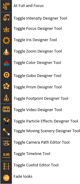
The design tools are individual toolbars that enable you to control certain parameters for selected fixtures. Currently these are the design tools:
Note: Design tools have the same properties as other toolbars and can be rearranged on the screen to improve the layout of the working area. You can also resize design tools by stacking them into columns so that they take up less space on the screen.
Begin by selecting the desired fixtures.
Select a fixture (or fixtures). You can select multiple fixtures by holding the CTRL key while clicking on the fixture symbols. You can also use fixture groups as described in Fixture groups.
Tip: You can also right-click and drag a box around a section of your drawing to select fixtures. This displays a context-sensitive menu displaying all the fixture types contained within that box. You can then easily select “All Mac500,” for example.
Result: The selected fixtures are highlighted in green.
Press CTRL+SHIFT+I to deselect all the currently selected fixture(s), and consequently select all the other fixtures previously not selected in DESIGN and LIVE modes.
Press CTRL+I to apply invert selection to fixtures, screens and LED walls in DESIGN and LIVE modes.
The Intensity tool provides many options for setting intensity levels.
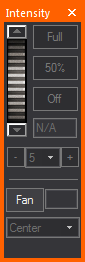
Click the buttons for the extreme settings of intensity: Full (100%) and Off (0%).
You can quickly adjust the intensity by using the Plus or Minus buttons to alter intensity by 5%, 10% or 25%.
Use the dial to achieve any of the settings in between. To use the dial, click and hold the dial while you move the mouse up or down. The chosen intensity level is displayed in the intensity box as you move the mouse. Use the up/down arrows located above and below the dial to change the value by one.
Alternatively, you can enter a specific percentage by typing the number in the intensity box, and then pressing ENTER. The beams will update instantly.
If multiple fixtures are selected, the intensity level entered is assigned to all fixtures. If you select multiple fixtures that have varying intensity levels, “N/A” appears in the intensity box.
The Fan feature enables you to select a group of fixtures, adjust the intensity as a group, and then spread the intensity out with a simple wheel. The fan allows for the distribution of intensity in the following configurations: Center, Left to Right, Right to Left, Chevron In, Chevron Out. Click the Fan button to set the wheel in Fanning mode (color changes), and then move the wheel up or down to change fanning spread of the selected fixtures.
The Focus tool works with fixtures that have variable pan and tilt parameters (i.e., automated fixtures). You must focus conventional fixtures in CAD mode.
Much like on a console, you can lock out Pan and/or Tilt from the Focus tool trackpad in order to prevent movement along a specific axis and help you focus your fixtures more effectively.
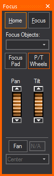
The Focus tool gives you the option of using it in either Box or Wheel mode, as shown below:
Box mode Wheel mode
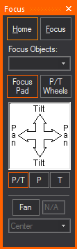
From the Pan and Tilt drop-down list, choose whether you want to lock out either the Pan or Tilt direction. When you do so, you cannot move the fixture beams along the locked out axis. For example, if you select Pan Only, you cannot focus your fixtures along the Tilt axis. To enable focusing in all directions, leave the default Pan and Tilt selected.
Note: This setting applies only to the trackpad itself, and will not prevent you from clicking-and-dragging the beam in a Wireframe view or assigning a Focus Position.
In the focus trackpad, click, hold, and drag the mouse to control the position of the light beam. The Home button resets the fixture to pan = 50% and tilt = 50%.
To send the fixture's beam to a specific location, click the Focus button, and then click in your wireframe drawing. Use the focus position drop-down list to focus the beams of light toward one of the Focus Positions that you created in CAD mode.
You can also use the Focus tool to assign automated fixtures to focus objects that you have drawn in CAD mode. For more information on focus objects, see Focus_objects.
Note: The Focus tool does not take into account the current viewing position or fixture settings. In one orientation, dragging to the right on the trackpad results in the beam moving left, but rotating the fixture 180 degrees and dragging to the right will cause the beam to move to the right. This effect occurs with both moving mirror and moving head fixtures.
The Fan feature enables you to select a group of fixtures, adjust their focus as a group, and then spread the pan/tilt out with a simple wheel. The fan allows for the distribution of pan/tilt settings in the following configurations: Center, Left to Right, Right to Left, Chevron In, Chevron Out.
Click the Fan button to set the wheel in Fanning mode (color changes), and then move the wheel up or down to change fanning spread of the selected fixtures.
Instead of using the Focus tool, you can also focus fixtures by clicking on the beam in CAD mode Wireframe views and dragging the beam to the desired location.
Note: Any focus object can be drawn and have fixtures assigned.
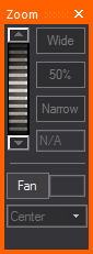
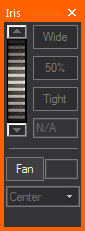
The Zoom and Iris tools both work the same way.
Use the buttons for the extreme settings of tight or wide.
Use the dial to achieve any of the settings in between. To use the dial, click and hold the dial while you move the mouse up or down. The chosen value is displayed in the box as you move the mouse. Use the up/down arrows located above and below the dial to change the value by one.
Alternatively, you can enter a specific percentage by typing the number in the zoom or iris box, and then pressing ENTER. The beam will update instantly.
The Fan feature enables you to select a group of fixtures, adjust the zoom or iris as a group, and then spread the zoom/iris out with a simple wheel. The fan allows for the distribution of zoom/iris settings in the following configurations: Center, Left to Right, Right to Left, Chevron In, Chevron Out. Click the Fan button to set the wheel in Fanning mode (color changes), and then move the wheel up or down to change fanning spread of the selected fixtures.
The Color tool offers many options for color selection.
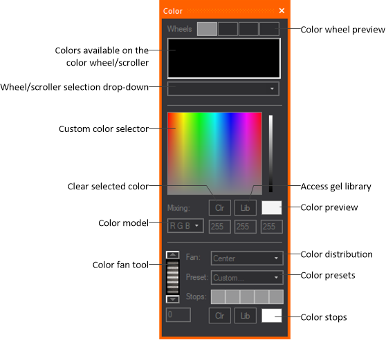
Click the custom color box or use the greyscale arrow to adjust your selection. The Color model values update automatically. The fixture's output depends on its capabilities. If the fixture has CMY or color mixing capabilities, the output is the exact color you selected. If the fixture is only equipped with a color wheel or a non-mixing scroller, the fixture will output the closest color to that selected, based on the available colors on the wheel.
The same principle works if you select a color from the library by clicking the Library button. The wheel/scroller selection drop-down list is as discussed for the gobo wheel. All of the available colors are displayed in the order in which they appear on the wheel or scroll.
To facilitate designing with various fixtures using different color mixing techniques, the Color tool also offers a drop-down list with three different color space models (RGB, CMY, HSI). If you know the RGB values of the desired color, you can enter them, and the custom color box will update. Or if you have the RGB value and want to convert it to the CMY equivalent, change the Color Mixing selection.
You can also preview the color selected at all times using the Color preview box. Double-clicking the Color Preview box has the same functionality as double-clicking the Color Picker area, but without affecting your position on the area.
Note: These are valid value ranges for the color spaces:
RGB Color Space: R (0-255), G (0-255),
B (0-255)
CMY Color Space: C (0-100), M (0-100), Y (0-100)
HSI Color Space: H (0-360), S (0-100), I (0-100)
The Color Fan feature enables you to select a group of fixtures, adjust the color as a group, and then spread the color out with a simple wheel. The fan allows for the distribution of color in the following arrangements: Center, Left to Right, Right to Left, Chevron In, Chevron Out.
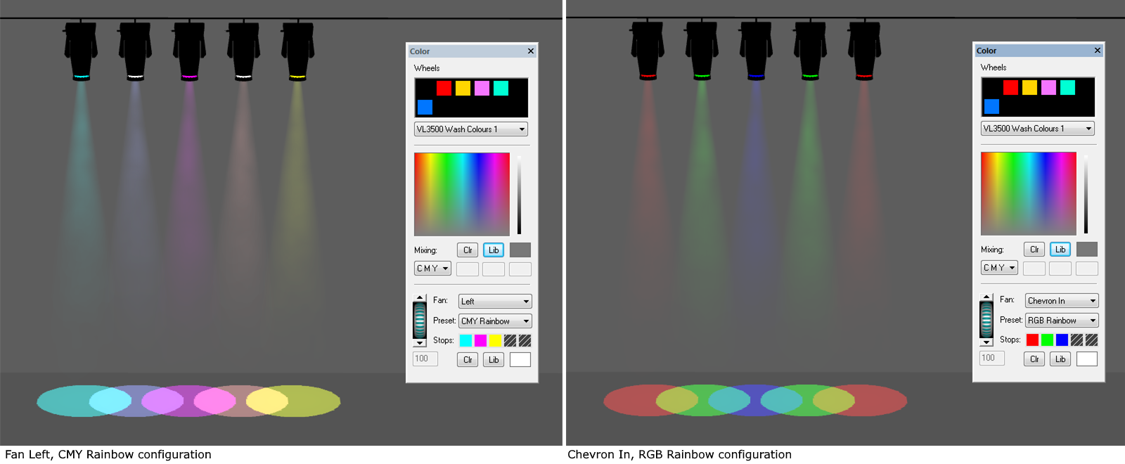
Color Fan offers predefined Color Presets with defined color stops, or custom color stops can be created (limit 5 color stops) using colors chosen from the color selector or gel library.
If a single LED type was specified in the LED Tape/Rope Wizard - Step 4 and wired to produce the same color/intensity output, the LED pixels will light up without color mixing. If the LED Tape or LED Rope was specified with color mixing from multiple types of LED clusters, you can light up the LED pixels with color mixing.
Tip: You can use Color Fan if the wiring and DMX control schema of the LED Tape or LED Rope allows. Color Fan will always apply from the start point to the end point of the LED Tape or LED Rope. You can easily create a Color Fan effect in reverse if required. If you select multiple LED Tape and LED Rope objects, all with the color mixing capabilities, required wiring and DMX control schema, you can use the Color Fan for all of them.
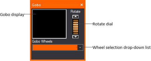
The Gobo and Prism tools work the same way. Specify the fixture type (if you have more than one selected), or the specific wheel to control (if that fixture type has multiple wheels) using the drop-down menu. Note that only fixtures with gobo or prism parameters appear on the list. Use the gobo/prism wheel scroll arrows to select the desired gobo/prism from the wheel. If no gobo/prism is desired, leave the wheel in the open slot.The dial will rotate this gobo if a rotating gobo is selected.
Streaming video enables you to bring a live or pre-recorded video stream into WYSIWYG and play it back while you set looks in DESIGN mode and while you precue in LIVE mode.
Notes:
After you draw the screen and attach the Video Source or Subsource or I-Mag camera to it (or to a 3D primitive, an LED Wall, or to a projector that you have inserted from the Fixtures library), you can use the Video Designer Tool (Video tool) in DESIGN mode to start the playback or stream. You can view the video in any of the Shaded views, using the controls on the Video Designer Tool to pause, fast forward, rewind, or stop the video.
Once you have the Video Source or subsource or I-Mag camera attached to an object, you must use the Video tool to control it. For more information, see To draw a screen, To configure a new video source for streaming video, and To create a new video source in the Video Manager, and To create an I-Mag camera in the Video Manager.
Note: If the video control is patched and DMX connected in LIVE mode, then you will not be able to control the Video Source or Subsource using any of the Video tool commands in DESIGN mode. Video Sources and Subsources can only be controlled by the Video tool when the DMX source is disconnected; therefore, you must first disconnect the applicable console device from within LIVE mode before using any of the Video tool commands.
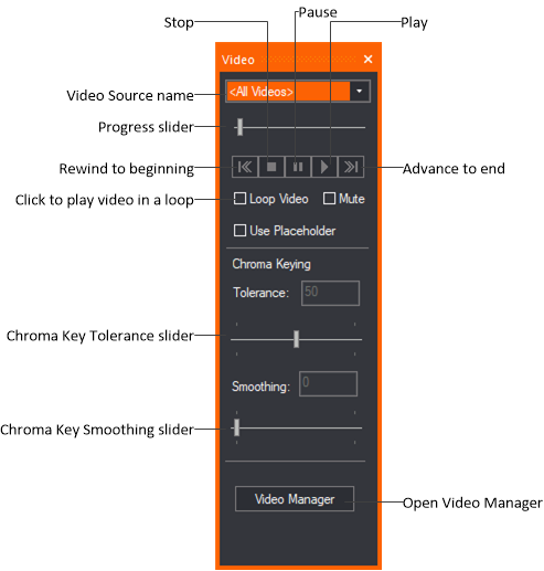
Note: When you click the Pause button, the frame of the video that is playing at the time is held on the video screen; when you click the Stop button, the video stops playing and the screen goes blank.
The Tolerance and Smoothing sliders will only be enabled (clickable) if you select a Video Source with enabled Chroma Key Property from the drop-down list.
Tolerance: Use the slider to increase or decrease the color range above and below the selected Chroma Color. The corresponding value appears in the adjacent box (0 to 100; default = 50).
Smoothing: Use the slider to adjust the edge smoothness between the subject and the solid color background. The corresponding value appears in the adjacent box (0 - 100; default = 50).
Tips:
For more information on Chroma Keying, see the Chroma_keying section.
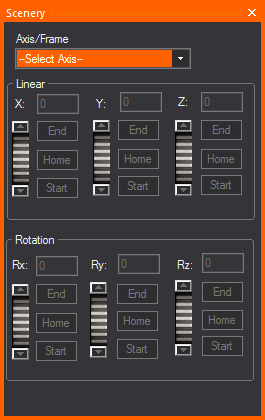
After drawing motion axes or frames and attaching objects to them, you can use the Moving Scenery Designer tool to make the object “move” along each axis.
You can simulate moving scenery by setting up looks containing motion axes or frames in DESIGN mode. Once you create the look and specify its fade time, use the Moving Scenery Designer tool to customize the look by selecting the appropriate motion axis or frame and the object’s starting position on it. Then create a second look, repeating the same procedure to set the object’s starting position on either the same axis or frame, or a different one (if there is more than one axis attached together).
When you switch from one look to the next, you can see the object move from the starting point of the first look, to the starting point of the second look within the time period that you define as the “fade time”.
After drawing motion axes/frames and attaching objects to them, you can use the Scenery tool to make the object “move” along each axis.
Note: You can also open the tool by clicking Design > Moving Scenery tool.
Use the Particle Effects tool to control particle effects simulation from particle generator machines inserted from the Particle System in the Library Browser. WYSIWYG provides small, medium, and large units for each smoke and flame machines from the Library Browser.
Result: The Particle Effects tool appears.
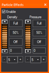
If Enable is selected and while the Particle Effects button is toggled ON in LIVE mode (with orange outline), any Smoke/Flame Machines that are supposed to be ON based on DMX input will produce the particle effects in LIVE mode. If Enable is not selected or the Particle Effects button is toggled OFF in LIVE mode (without orange outline), no particle effects will appear in any Shaded view.
 Particle Effects ON (with orange
outline);
Particle Effects ON (with orange
outline);  Particle Effects OFF (without orange outline)
Important Notes:
The Pressure dial is disabled for flame machines and CO2 since they do not have a dynamic range option; the distance that flames and CO2 plumes shoot out is controlled from their Properties > Fixture tab > Options sub-tab.
Note: The particles created will not dissipate immediately once smoke machines are turned off.
Tips:
Use the Footprint tool to change a footprint's focus distance for automated fixtures in the Shaded view of DESIGN mode, in effect making the focus of the footprint "hard" or "soft".
Note: In this release of WYSIWYG, this feature is available in CAD and DESIGN modes only: Footprint Focus is configurable for conventional fixtures in CAD mode and configurable for automated fixtures in DESIGN mode (see To focus a footprint for a conventional fixture). Once configured, all fixtures can be visualized in DESIGN mode. In an upcoming release, the Footprint Focus feature will be extended to function in LIVE mode like all other Designer tools.
Result: The Footprint tool appears.
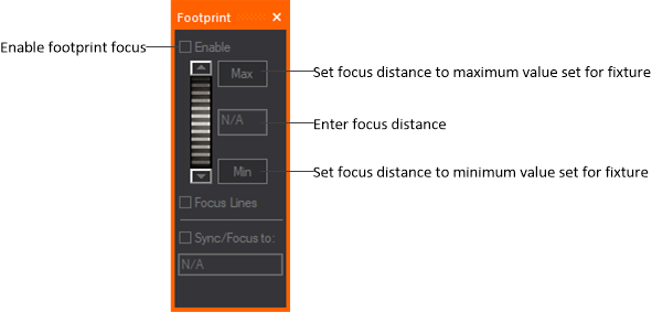
Note: The effect is visible in the Shaded view when Footprint Focus is enabled on the Simulation tab of the View Options window.
In Shaded view, Highlight sets the currently selected fixture(s) to an open beam at 100% full intensity temporarily, without changes to the fixture’s saved settings.
Highlight can be accessed from the Design menu or the Fixture Selection toolbar.
Highlight is useful when identifying a single fixture or a small selection of fixtures within a large and complex plot.
Tip: You may also use the Highlight tool on the Fixture Selection toolbar or use the hotkey H on your keyboard.
![]() The Highlight button.
The Highlight button.
Result: The selected fixture(s) is highlighted showing an open beam at full intensity.
Result: The next fixture selected is highlighted showing an open beam at full intensity, and the previously highlighted fixture goes back to its previous state.
Note: The displays in the Design tools windows associated with the highlighted fixture(s) will appear in white/clear.
This feature offers the ability to display the intensity level applied to a fixture and appears as a Fixture Attribute. The intensity level value is displayed as part of the Fixture Symbol text in the wireframe views in CAD, DESIGN, and LIVE modes; and in Layouts in the PRES mode.
Result: The Update Intensity Labels tool is enabled and the current intensity value applied to a fixture is displayed as part of the Fixture Symbol text.
Result: The intensity value displayed in Layouts (PRES mode) and Wireframe views is updated according to the current intensity level applied to the fixture.
Result: The intensity value displayed in Layouts (PRES mode) and Wireframe views is updated according to the current intensity level applied to the fixture.
![]() © CAST Group of Companies Inc., 2002-2024 All rights reserved.
© CAST Group of Companies Inc., 2002-2024 All rights reserved.