Object Settings
The Object Settings section in Document
Options contains settings that affect CAD objects such as fixtures,
hang structures and drawn objects.
Fixture
Settings tab
Options on the Fixture
Settings tab determine how detailed simulation and wireframe
views are. These options can affect the speed of beam simulation in views.
For more information on simulation options, see Visualization.
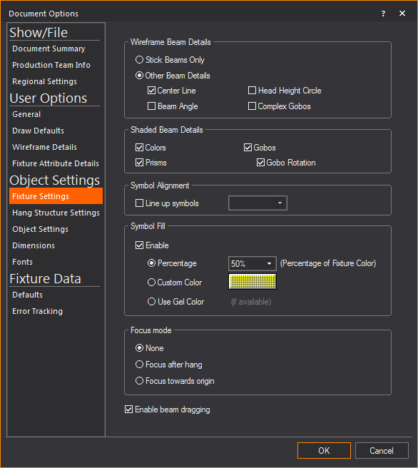
Wireframe Beam Details
Options to simulate effects with Wireframe
view beams.
- Stick Beams Only:
Select this checkbox to only display beams as stick beams. Selecting
this option might increase system performance.
Note: The
Stick Beam option only applies to the representation of beams in Wireframe
views. Beam visualization in Shaded views is not affected.
- Other Beam Details:
Select this checkbox to enable other details for beams.
- Center Line: Select
this checkbox to draw a point from the fixture to the point on the
stage where the center of the beam hits. If the fixture has CMY color
mixing, the line will change color to match the output from the console.
- Beam Angle: Select
this checkbox to display the photometric data of the fixture’s beam
angle instead of the field angle.
- Head Height Circle:
Select this checkbox to enable checking the light coverage at a certain
height (the height of the performer).
- Complex Gobos:
Select this checkbox to display complicated gobo patterns with details
and coloring.
Shaded Beam Details
Options to simulate effects with Shaded
view beams.
- Colors: Clear
this checkbox to ignore color settings and have all beams displayed
as open-white.
- Prism: Select this
checkbox to simulate prism effects. This might increase the number
of lines that WYSIWYG has to draw, thus slowing down processing power.
- Gobos: Gobo wheels
often take a lot of processing power and can slow down the refresh
rate of other fixtures’ updates unnecessarily. If you are concerned
about cue timing, clear this checkbox to disable gobos.
- Gobo Rotation:
Select this checkbox to simulate gobo rotation. This option can slow
down the refresh rate substantially as gobos can be rotating even
when the fixture’s intensity is at zero.
Symbol Alignment
Options for organizing symbols.
- Line up symbols:
Select this checkbox to line up fixture symbols at specific angles,
and then select an increment from the drop-down list. Symbols will
shift from their focused position to the nearest increment of the
chosen angle. For example, symbols will be drawn in one of four directions
when the increment is set to 90 degrees. This setting does not affect
the focus of the beam; rather it is intended for the “cleanliness”
of the printed plot.
Symbol Fill
Options for fixture symbols to be filled
with a choice of colors and fill percentage.
- Enable: Select
this checkbox to enable Symbol Fill.
- Percentage: Select
this radio button if you wish to fill using the same hue of the Fixture
Symbol, and select the percentage from the drop-down list for the
hue intensity.
- Custom Color: Select
this radio button and click the cell to choose a different color.
- Use Gel Color:
Select this radio button if you wish to fill using the gel color that
is attached to the fixture. Gel color will be displayed if only one
gel is applied to the fixture.
Note: Once
the Symbol Fill feature is enabled, the 2D fixture symbols will be displayed
as filled in CAD Wireframe 2D views only, and not in Isometric view.
Focus mode
Allows you to choose to focus a fixture
as you hang it in your drawing. Specify one of the following options to
set how a fixture will react after you hang it in a plot:
- None: This setting
indicates that you can continue to hang fixtures uninterrupted.
- Focus after hang:
If enabled, you will be prompted to focus each fixture as you hang
it. Once the fixture is focused, you can continue hanging other fixtures.
- Focus towards origin:
If enabled, the fixtures that you hang are automatically focused towards
the user origin.
- Enable beam dragging:
Select this checkbox to enable click and drag positioning of beams
in CAD, DESIGN, and LIVE modes. This option is also available on the
CAD Options toolbar in CAD, DESIGN,
and LIVE modes.
Hang
Structure Settings tab
Options on the Hang
Structure Settings tab affect how hang structures, such as
pipes and truss, are placed or drawn in CAD mode.
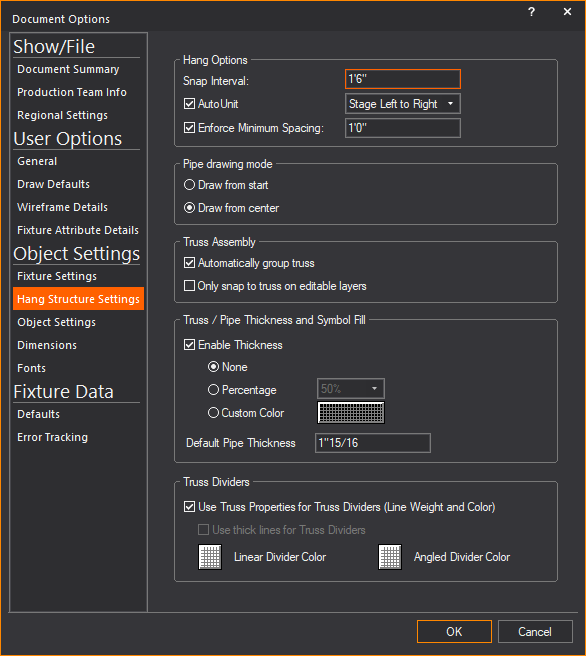
Hang Options
Options that affect how fixtures are placed.
- Snap Interval:
If Pipe Snap is enabled (in the
Draw Defaults tab), the number
entered into the field will be used as the interval used for snap
spacing.
- AutoUnit:
Select this checkbox to automatically
assign a unit number to each fixture that is hung. This option is
available for pipes only. It does not apply to truss.
- Auto-Unit Order:
The direction in which fixtures will be assigned a number, either
Stage Left to Right or House Left to Right.
- Enforce Minimum Spacing: Type the minimum
spacing between fixtures. This option prevents you from hanging the
fixtures too close to one another.
Pipe drawing mode
Options that affect how pipes are drawn.
- Draw from start:
Select this checkbox to have pipes drawn by specifying the start point
and the end point (from one extremity of the pipe to the other).
- Draw from Center:
Select this checkbox to have pipes drawn by specifying the center
point and one end point or extremity of the pipe.
Truss Assembly
Options that affect how truss is assembled.
- Automatically group truss:
Select this checkbox to group truss objects together in a similar
manner to choosing from the
menu. This option is helpful
in that it treats the truss as a single unit and allows you to perform
actions more effectively on multiple objects. If you want to edit
one truss object, you must first use the command
on the menu to remove the grouping
from the truss objects.
- Only snap to truss on
editable layers: Select this checkbox to enable a truss section
to automatically snap onto truss sections in layers that were set
as editable in the Layer Database.
Truss/Pipe Thickness and Symbol Fill
Options that affect how truss and pipe
symbols are displayed in Wireframe.
- Enable Thickness:
Select this checkbox to display Truss and Pipe symbols with thickness
in 2D CAD Wireframe views and in associated paperwork views (Not in
isometric views). Clear this checkbox to display the truss and pipe
objects as line drawings.
- None: Select this
checkbox to disable Symbol Fill, and the 2D truss and pipe objects
will not be filled when displayed in Wireframe.
- Percentage: Select
this radio button if you wish to fill using the same hue of the truss
or pipe object, and select the percentage from the drop-down list
for the hue intensity.
- Custom Color: Select
this radio button and choose a custom color from the color select
box as fill color for the truss or pipe object.
- Default Pipe Thickness:
Type a new value to change the default thickness of the pipes in your
drawing.
Truss Dividers
Options that affect how truss dividers
appear.
- Use Truss Properties for
Truss Dividers (Line Weight and Color): Select this checkbox
to have truss dividers match the appearance of their truss. Clear
this checkbox to define custom colors for the dividers.
- Use thick lines for Truss
Dividers: Select this checkbox if truss dividers will not use
the same properties as the truss. Thick lines are used for truss dividers.
Use the buttons below to change the color of dividers.
- Linear Divider Color:
Click this button to choose a custom color for linear dividers.
- Angled Divider Color:
Click this button to choose a custom color for angled dividers.
Object
Settings tab
Options on the Object
Settings tab affect how various simple objects are drawn in
CAD mode.
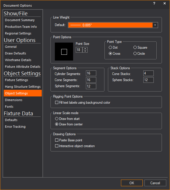
- Line Weight: Select
from this drop-down list, the default thickness of lines created.
Point Options
Options that affect how points are drawn
in CAD mode.
- Point Size: Sets
the default size for all points. You can view a sample of the chosen
size in the box to the right.
- Point Type: Indicates
the default point type in your show document. You can choose to display
points as a Dot, Cross,
Square, or Circle.
Segment Options
Options that affect how multi-segment objects
are drawn.
- Cylinder Segments:
The number of segments into which you want to break a cylinder.
- Cone Segments:
The number of segments into which you want to break a cone.
- Sphere Segments:
The number of segments into which you want to break a sphere.
Stack Options
Options that affect how objects are divided.
- Cone Stacks: The
number of horizontal divisions into which you want to break a cone.
- Sphere Stacks:
The number of horizontal divisions into which you want to break a
sphere.
Rigging Point Options
Options that affect how rigging points
are displayed.
- Fill text labels using
background color: Select this checkbox to display Rigging Point
labels filled with the Wireframe, Layouts, or New Plots background
color.
Linear Scale mode
Options that affect how linear scales are
drawn.
- Draw from start:
Select this checkbox to have linear scales drawn by specifying the
start point and the end point (from one extremity of the pipe to the
other).
- Draw from Center:
Select this checkbox to have linear scales drawn by specifying the
center point and one end point or extremity of the pipe.
Drawing Options
Options that affect how linear scales are
drawn.
- Paste Base point:
Select this checkbox to enter a base point before an object is copied
or cut. This will be the object’s reference point for paste commands.
Clear this checkbox to allow the base point to be the insertion point
of the object.
- Interactive object creation:
Select this checkbox to allow yourself to draw objects using the mouse
instead of entering values in dialog boxes.
Dimensions
tab
Options on the Dimensions tab
affect how various dimensions are drawn by default.
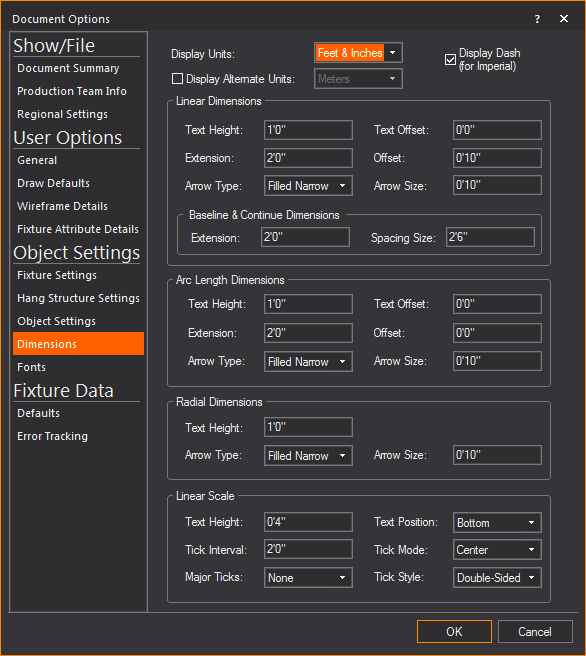
- Display Units: The type of measurement unit displayed
for dimensions in CAD mode. Choose the default imperial measurement
units between Feet & Inches or
Inches.
- Display Dash (for Imperial):
When this option is enabled, a dash is displayed between foot and
inches in imperial measurements, e.g. 6’-8 3/4”.
- Display Alternate Units: Select this checkbox to display a second
measurement with your dimensions, in the alternate unit. For example,
if metric is your set unit but also wish to display all of your dimensions
with both metric and imperial values, enable this option. The drop-down
list offers the display unit options for the alternate unit displayed.
Note: In the
Draw Defaults window, if Imperial is
the selected default measurement unit, the Display
Units will be Imperial and
the Display Alternate Units will be
Metric and vice versa.
Linear Dimensions
Options to affect the default settings
of linear dimensions.
- Text Height: The
default text height for linear dimensions object in CAD mode.
- Text Offset: Sets
the default distance of the text above or below the dimension line
in CAD mode.
- Extension: The
default length of the extension lines for linear dimensions in CAD
mode.
- Offset: Sets the
default offset value for linear dimensions in CAD mode. The offset
is the distance between the extension lines and the object being measured.
- Arrow Type: Select
the default arrow type for linear dimensions in CAD mode. There are
several styles available to choose from.
- Arrow Size: Select
the default size of the arrow head for linear dimensions in CAD mode.
Baseline & Continue Dimension
- Extension: The
default length of the extension lines for both Baseline and Continue
Dimensions.
- Spacing Size: The
default length of the space between the stacked and subsequent baseline
dimensions from the same extension base line.
Arc Length Dimensions
Options to affect the default settings
of arc length dimensions.
- Text Height: The
default text height for arc length dimensions in CAD mode.
- Text Offset: Sets
the default distance of the text above or below the dimension line
in CAD mode.
- Extension: The
default length of the extension lines for arc length dimensions in
CAD mode.
- Offset: Sets the
default offset value for arc length dimensions in CAD mode. The offset
is the distance between the extension lines and the object being measured.
- Arrow Type: Select
the default arrow type for arc length dimensions in CAD mode. There
are several styles available to choose from.
- Arrow Size: Select
the default size of the arrow head for arc length dimensions in CAD
mode.
Radial Dimensions
Options to affect the default settings
of radial dimensions.
- Text Height: The
default text height for radial dimensions in CAD mode.
- Arrow Type: Select
the default arrow type for radial dimensions in CAD mode. There are
several styles available to choose from.
- Arrow Size: Select
the default size of the arrow head for radial dimensions in CAD mode.
Linear Scale
Options to affect the default settings
of linear scales.
- Text Height: The
default text height for linear scales in CAD mode.
- Text Position:
Select the default position of text that appears for linear scales.
- Tick Interval:
Select the default interval at which ticks will appear on linear scales.
- Tick Mode: Select
the default mode of which ticks appear on linear scales.
- Major Ticks: Select
how major ticks will appear on linear scales.
- Tick Style: Select
the default tick style that will appear on linear scales.
Fonts
tab
Options on the Fonts tab
affect how text is displayed by default on dimensions, scales and labels.
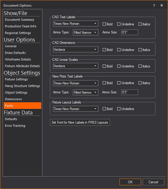
CAD Text Labels
The default setting of CAD Text Labels
text.
- Font: The default
font used for the text. Select the desired font type from the drop
down menu.
- Bold: Select this
checkbox to make the default text bold.
- Underline: Select
this checkbox to make the default text underlined.
- Italics: Select
this checkbox to make the default text italicized.
- Arrow Type: The
style of arrow head used on the dimension.
- Arrow Size: The
size of the arrow head used on the dimension.
CAD Dimensions
The default setting of CAD Dimensions text.
- Font: The default
font used for the text. Select the desired font type from the drop
down menu.
- Bold: Select this
checkbox to make the default text bold.
- Underline: Select
this checkbox to make the default text underlined.
- Italics: Select
this checkbox to make the default text italicized.
CAD Linear Scales
The default setting of CAD Linear Scales
text.
- Font: The default
font used for the text. Select the desired font type from the drop
down menu.
- Bold: Select this
checkbox to make the default text bold.
- Underline: Select
this checkbox to make the default text underlined.
- Italics: Select
this checkbox to make the default text italicized.
New Plot Text Labels
The default setting of New Plot Text Labels
text.
- Font: The default
font used for the text. Select the desired font type from the drop
down menu.
- Bold: Select this
checkbox to make the default text bold.
- Underline: Select
this checkbox to make the default text underlined.
- Italics: Select
this checkbox to make the default text italicized.
- Arrow Type: The
style of arrow head used on the dimension.
- Arrow Size: The
size of the arrow head used on the dimension.
Fixture Layout Labels
The default setting of Fixture Layout Labels
text.
- Font: The default
font used for the text. Select the desired font type from the drop
down menu.
- Bold: Select this
checkbox to make the default text bold.
- Underline: Select
this checkbox to make the default text underlined.
- Set Font for New Labels
in Pres Layouts: The default setting of Set Font for New Labels
in Pres Layouts text. Click this button to change the settings.