Camera paths
Once you draw a Camera Path in CAD Mode,
you can use the Camera Path Editor and the Timeline tool in DESIGN or
LIVE mode to define the time interval between two nodes along the path.
If there are Camera Targets inserted in the file, you can also specify
when the camera should follow a camera target. Finally, you can also define
the orientation and field angle of the Camera at the current node position.
Once you have defined the time intervals
and camera’s orientation, you can open the Timeline tool and watch the
Camera Path play in Shaded view. Camera Path playback is also simulated
in Full Screen mode.
You can also patch a Camera Path to a DMX
universe and then control the camera’s movement through a console. For
details, see Patching
camera paths.
Using
the Camera Path Editor
Once you create a Camera Path in CAD mode,
follow the steps in this section to define the time intervals between
the nodes on the path, change camera behavior, assign targets to camera
nodes, and reposition nodes in space. For details on drawing Camera Paths,
see Drawing
camera paths.
Camera Path Editor window
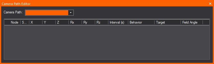
Camera Path Editor columns
- Node: This column gives
you the Node number of the nodes on your Timeline.
- Shortest Path: When
the Shortest Path checkbox is
selected for a node, it forces the camera to rotate as little as possible
when moving between two nodes on your timeline. When the Shortest
Path checkbox is cleared for a node, the camera will take
the longer of the two directions as it rotates to aim at the next
node's target. This applies to Roll, Pitch and Yaw.
- X, Y, and Z Columns: The
X, Y, and Z columns in the Camera Path Editor are editable position
information for each of the nodes on your timeline. You may enter
in distance values into these fields to re-position your nodes as
you see fit.
- Rx, Ry, and Rz Columns: These
columns represent the rotation around each of the X, Y, and Z axes
in WYSIWYG. These columns are non-editable, but allow you to get positional
information from your nodes.
- Rx, or Rotation around the X Axis = PITCH [tilting
forward and backward]
- Ry, or Rotation around the Y Axis = ROLL [tilting
side to side]
- Rz, or Rotation around the Z Axis = YAW [also
called Heading or Direction]
- Interval: A
node’s Interval is how long it takes in seconds to get from one node
to another. For example, if the timing on node 2 is ten seconds (10s),
then the camera would move for ten seconds before reaching node 2.
- Behavior: Behavior
is the camera’s movement and direction behavior as it relates to the
Camera Path. There are three types of Camera Behavior:
- Follow Path: The
camera will follow straight along the path, not deviating in any way
possible from the path as it travels between nodes.
- Follow Target: The
camera will always point at an assigned Camera Target if this behavior
is chosen for a node.
- User Defined: This
option allows the camera to behave exactly as specified by a user,
meaning that the camera will point wherever you point it when the
User Defined behavior is chosen.
- Target: Each
node can be assigned a different target when the Follow Target behavior
in the Behavior column is chosen. The Target column is a drop-down
list for choosing different targets in your drawing.
- Field Angle: This
option allows you to enter in different field angles for each node.
To use the Camera Path
Editor
- In Wireframe view, from the menu,
choose .
- In the Camera Path Editor,
from the Camera Path drop-down list,
select the Camera Path that you want to edit.
- In the Interval column, adjust the timing for
each node along the path, specifying when you want the camera to be
at that node.
- If you have placed targets along the path, and
you want the Camera to follow a target at a particular node, in the
Target column click in the cell corresponding to the node and, from
the drop-down list that appears, select Follow
Target. Then, click in the adjacent Target cell to select the
target.
- To define the orientation and field angle of
the Camera at a particular node along the path, in the Camera Target
column, click in the cell corresponding the node, and then select
User Defined.
- Once you have defined the time intervals, you
can use the Timeline tool to watch the Camera Path play in the Shaded
view. For details, see below.
Visual
Camera Path Builder tool
The Visual Camera Path Builder tool allows
you to create a Camera Path on the fly while you move the Camera around
your space. This tool essentially works by placing a node at the Camera’s
current position once you’ve told WYSIWYG that you are satisfied with
the Camera’s current placement on screen.
Note: The
Visual Camera Path Builder tool is
disabled if the Shaded View Camera Control was
set to Other 3D Applications in the
General tab of the Application
Options window.
To use the Visual Camera Path Builder tool
- Right-click in the Shaded view and select .
- Once you’ve started the Visual Camera Path Builder,
you’ll be prompted to name your new path, add it to the Camera layer
(or a layer of your choosing), and create the first node based on
the Camera’s current position.
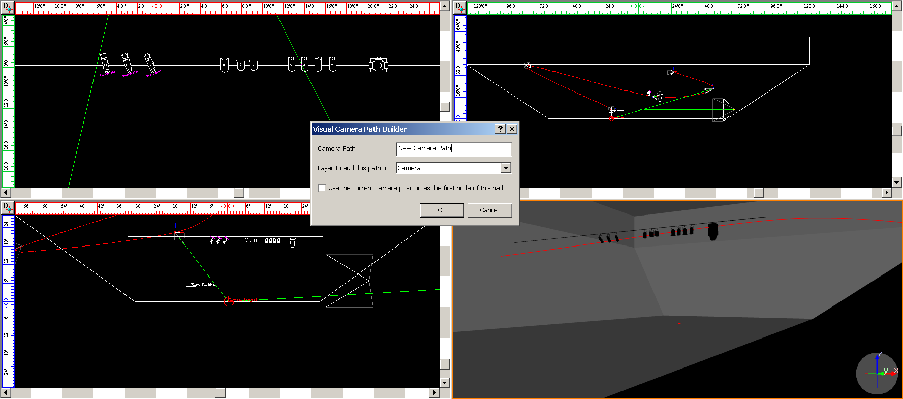
- Once you click OK in
the dialog box, you will then be in Visual Camera Path Editor mode.
Maneuver the Camera around the space, and when you want to create
a new node based on your Camera’s position, right-click in the Shaded
view and choose the . At this
point, you can also Abort your Camera Path in the Visual Camera Path
Builder tool.
- Move the Camera and right-click every time you
would like to create a new node from your Camera’s current position
in space.
- When you have created as many nodes as you would
like to have in your Camera Path, right-click again in the Shaded
view and choose .
- At this point, you can also Abort your Camera
Path, or you can choose to Close the Camera Path from your current
view, which will create a seamless loop on the Camera Path. When you
are finished with the Visual Camera Path Builder tool, you will automatically
exit the Visual Camera Path Builder tool mode.
To use the Timeline tool
Once you have adjusted the timing of a
Camera Path with the Camera Path Editor, switch to the Shaded view to
watch the camera move along the path with the Timeline tool.
This tool enables you to watch the timing in slow motion, regular speed,
or up to four times the speed.
Notes:
- Camera Path playback is also simulated in Full
Screen mode.
- Nodes of existing Camera Paths can be edited
from a Shaded view when the Timeline's Previous Node or Next Node
buttons are used; they can only be edited while playback is paused.
- In Shaded view, click >
.
Result: The
Timeline tool appears.
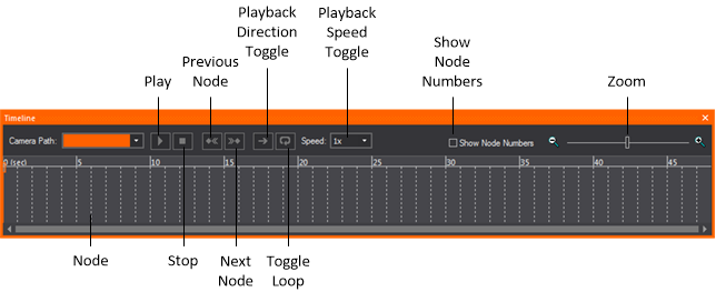
- Use the controls to watch the Camera move along
the path you have defined:
- Play: Click to
start the Camera Path simulation in the Shaded view. While this plays,
the red line moves along the timeline to display its current position.
You can click on the red line indicator and scrub along the timeline,
which updates the red line and the Camera simulation at the corresponding
point along the path.
- Stop: Click to
stop the camera.
- Previous Node:
Click to switch back to the previous node on the path.
- Next Node: Click
to move to the next node on the path.
- Toggle PlayBack Direction:
Click to switch the direction of the camera on the path.
- Toggle Loop: Click
to keep the camera moving on the path in a continuos loop.
- Adjust Playback Speed:
Click to choose the playback speed.
- Show Node Numbers:
Click to show the node numbers in the timeline.
- Zoom: Use the
slider to zoom in or out on the timeline.
Note: When
the DMX Control for Cameras/Camera Paths is enabled in Camera
Manager, the controls in the Timeline tool
are disabled in LIVE mode, as DMX will be in control of all Camera Path
playback and settings.