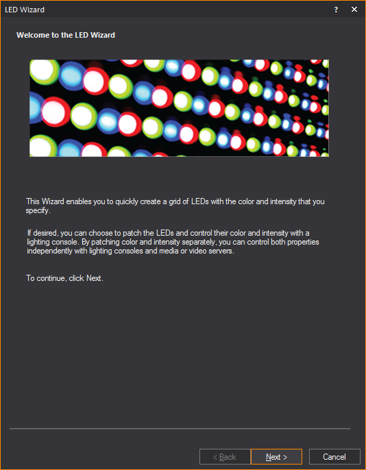
LED
Wizard
This Wizard enables you to quickly create
a grid of LEDs that simulates LED walls or panels, as well as LED webs,
star cloths and video curtains. The grid can have Image or Video Sources
applied to it, or can be patched to DMX universes for control via LED
mapping software or lighting consoles.
To use the led
wizard
- From the menu,
choose .
Result: The
LED Wizard appears.
- Click Next.
Result: The
Dimensions and style window appears.
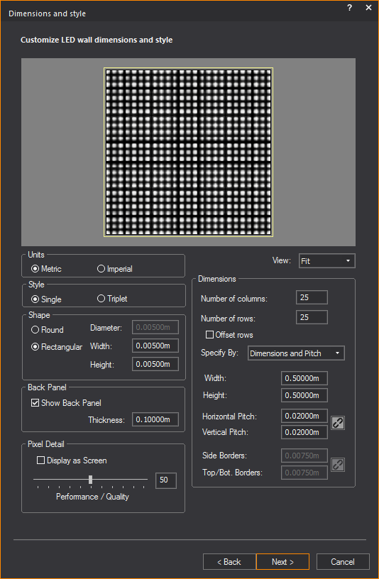
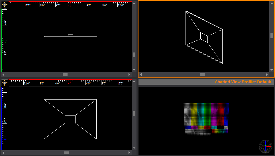
- Use the options in the View drop-down
list to control the "zoom level" of the preview area:
- Fit: Choose this
option to fit the grid to the preview area.
- Zoom: Choose this
option to zoom in on the center of the grid, to check the image or
video that was mapped to the pixels.
- Corner: Choose
this option to zoom in on the lower-left corner of the grid. This
is useful for checking how the frame appears in relation to the rest
of the grid.
Note: The
preview of the LED device will update as you provide its style and dimensions
values. This helps you visualize your LED panel or wall before you move
onto the next step.
- In the Units section,
choose the measurement unit you want to use in the grid you are creating.
By default, the Units section
is set to Metric.
- Metric: Choose
this option to specify the measurements in meters.
- Imperial: Choose
this option to specify the measurements in feet and inches.
- In the Style section,
choose the style of LEDs that you want to use in the grid you are
creating:
- Single: Choose
this option to use single LEDs which produce (all) three colors—Red
and Green and Blue.
- Triplet: Choose
this option to use LED clusters comprised of three LEDs, each of which
produces a single color—Red or Green or Blue).
- In the Shape section,
choose the shape of the individual LEDs to use in the grid, and then
specify their size:
- Round: Choose
this option if you want the Single LED or each element of a Triplet
to be round, and then type the diameter of the LEDs in this grid.
- Rectangular: Choose
this option if you want the Single LED or each element of a Triplet
to be rectangular, and then type the width and height of the LEDs
in this grid.
- In the Dimensions section,
define the layout of the grid by specifying the number of rows and
columns of LEDs:
- Number of columns:
Type the number of columns in the grid.
- Number of rows:
Type the number of rows in the grid.
- Offset rows: Select
this checkbox to offset the rows in the grid by one-half of the Horizontal
Pitch (described below).
- Use the Specify By drop-down
list and the fields below it to select the parameters of the device
(i.e., LED panel, LED wall, LED web, video wall, etc.) that you will
use to define this LED grid:
- Choose Dimensions and
Pitch to define the grid’s height and width and pixel
pitch. (The pitch is the center-to-center distance between LEDs in
the grid. The height and width are the overall height and width of
the device as seen from the front—i.e., the height and width of an
LED panel or LED wall.) When you choose this option, the LED Wizard
will calculate the width of the device’s Borders for you.
- Width: Type
the overall width of the device being simulated.
- Height: Type
the overall height of the device being simulated.
- Horizontal Pitch:
Type the horizontal center-to-center distance between LEDs in
the grid of the device being simulated.
- Vertical Pitch:
Type the vertical center-to-center distance between LEDs in the
grid of the device being simulated.
Tip: Since,
in many cases, LED panels or walls have the same horizontal and vertical
pixel pitch, you may click the Lock button
to apply the same value to both.
 The
Lock button.
The
Lock button.
- Choose Dimensions and
Borders to define the height and width of the device being
simulated, and its borders’ horizontal and vertical sizes. (The height
and width are the overall height and width of the device as seen from
the front—i.e., the height and width of an LED panel or LED wall.
The border is the distance between the edge of the device and the
edge of the first row and/or column of LEDs in the grid.) When you
choose this option, the LED Wizard will calculate the grid’s pixel
pitch for you.
- Width: Type
the overall width of the device being simulated.
- Height: Type
the overall height of the device being simulated.
- Side Borders:
Type the distance between the left edge of the device being simulated
and the edge of the left-most column of LEDs. The same value will
be applied to the right side of the device, between its right
edge and the edge of the right-most row of LEDs.
- Top/Bottom Borders:
Type the distance between the top edge of
the device being simulated and the edge of
the top row of LEDs. The same value will be applied to the bottom
of the device, between its bottom edge and
the edge of the
bottom row of LEDs.
Tip: Since,
in many cases, devices such as LED panels or walls have the same-size
horizontal and vertical borders, you may click the Lock button
to apply the same value to both.
 The Lock button.
- Choose Pitch and Borders to
define the pixel pitch and borders’ horizontal and vertical sizes
of the device being simulated. (The pixel pitch is the center-to-center
distance between LEDs in the grid. The border is the distance between
the edge of the device and the edge of the first row and/or column
of LEDs in the grid.) When you choose this option, the LED Wizard
will calculate the device’s height and width for you.
- Horizontal Pitch:
Type the horizontal center-to-center distance between LEDs in
the grid of the device being simulated.
- Vertical Pitch:
Type the vertical center-to-center distance between LEDs in the
grid of the device being simulated.
- Side Borders:
Type the distance between the left edge of the device being simulated
and the edge of the left-most column of LEDs. The same value will
be applied to the right side of the device, between its right
edge and the edge of the right-most row of LEDs.
- Top/Bottom Borders:
Type the distance between the top edge of
the device being simulated and the edge of
the top row of LEDs. The same value will be applied to the bottom
of the device, between its bottom edge and
the edge of the
bottom row of LEDs.
Tip: Since,
in many cases, LED panels or walls have the same-size horizontal and vertical
pixel pitch as well as borders, you may click the Lock
button to apply the same value to both.
 The Lock button.
- In the Back Panel
section, choose the back panel settings for LED Wall.
- Show Back Panel:
Enable to create a black back panel for the LED Wall. This option
is enabled by default.
- Thickness: Type
in the thickness of the back panel.
Tip: After
the LED Wall is inserted the file, the Back Panel settings can still be
changed from the properties menu of the LED Wall.
- In the Pixel Detail section,
- You can use the Pixel
Detail slider to control the LED Wall quality vs. performance
setting. An increase in pixel detail will result in a decrease in
performance.
or
- If the source of your LED wall is color, image
or video, you can select the Display as Screen checkbox
to display the LED wall as a screen with a projected image instead
of a detailed grid of LED pixels forming the image.
Display as Screen does
not work if the source of the LED wall is Dynamic DMX patch.
- Click Next.
Result: The
Apply Content window appears.
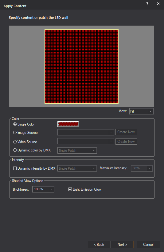
- In the Color section,
select what this LED grid will display:
- Single Color:
Choose this option in order to have the grid display the selected
color in all modes; click the color box next to this option to select
the color to be displayed.
- Image Source:
Choose this option in order to have the grid display the image from
an Image Source or Subsource that you created in the Image
Manager, and then select the Image Source or Subsource to display
from the drop-down list. (For more information on using the Image Manager, see Image Manager.)
Click Create New to launch the
Image Manager to create a new
image source or subsource.
Tip: For optimum
results, the number of rows and columns of this LED grid should be proportional
to the dimensions of the Image Source or Subsource being selected here.
- Video Source:
Choose this option in order to have the grid display the video from
a Video Source or Subsource, that you created in Video
Manager.
From the drop-down list select the Video
Source or Subsource to display. (For more information on using the Video Manager, see Video Manager.)
Click Create New to launch the Video Manager to create a new Video
Source or Subsource.
IMPORTANT: When
a video is used on an LED grid, if that video is not playing, that grid
will not appear in Shaded view in DESIGN and LIVE modes. To play the video,
use the Video Designer tool in DESIGN or LIVE mode.
Tip: For optimum
results, the number of rows and columns of this grid should be proportional
to the dimensions of the Video Source or Subsource being selected here.
- Dynamic Color by DMX:
Choose this option to control the color of the LEDs in this grid via
DMX (by connecting to a lighting console or to LED mapping software),
and then select how the color channels should be patched:
- Single Patch:
Select this option from the drop-down list in order to control
the color of this entire grid with a single set of DMX channels.
After selecting this option, if you choose red on your console,
every point source in the entire grid will be red.
- Multi Patch:
Select this option from the drop-down list to control individual
LEDs in this grid via separate sets of DMX channels. After selecting
this option, you will have the ability to control the color mix
for every LED in the grid individually.
Tip: Select
this option when controlling the LED grid from specialized LED mapping
software.
Note: If this
option is selected, the LEDs will appear in the color of the Layer on
which this grid is located in all Shaded views, except those in LIVE mode
(where they will appear in the color provided by the incoming DMX data).
- In the Intensity section,
you have the option to select whether or not you wish to have dynamic
control of the grid intensity, via DMX for LIVE mode.
Note: This
option applies to LIVE mode only. The Brightness value will set the intensity
of the LED grid for all other modes.
- Single Patch:
Select this option from the drop-down list in order to control the
intensity of the entire grid with a single DMX channel.
- Multi Patch: Select
this option from the drop-down list in order to individually control
the intensity of each LED in this grid via individual DMX channels.
- Maximum Intensity:
Select the maximum intensity value of the LEDs in this grid when connected
to a console and viewed in LIVE mode.
IMPORTANT: This
value applies to the maximum intensity of the LEDs in LIVE mode. This
is intended to control maximum brightness of each LED grid, because some
LEDs are brighter than others. For example, if you set one LED grid to
100% and another LED grid to 50%, when you then control them via DMX in
LIVE mode and set the console channel to full (255), the LED grid with
Maximum Intensity set to 100% will be brighter than the one set to 50%.
- In the
Shaded View Options section, set
the level of overall brightness and glow effect of the LED grid in
the Shaded views of CAD, DESIGN and LIVE modes.
- Brightness: From
the Brightness drop-down list,
set the overall brightness of the LED grid.
Note: If
Dynamic Intensity by DMX is disabled,
the static intensity that you define will also apply in LIVE mode.
- Light Emission Glow:
Select this checkbox to display in Shaded view the light emission
glow effect from the LED array.
Note: Glow must be enabled in the Light
Emission section of the Visual Effects tab
in the View Options window to show
the light emission glow effect from objects in Shaded view.
- Click Next.
Result: If
the content of your LED grid is controlled by a Single Color, Image Source
or Video Source, you are Finished. Otherwise, you’ve selected to control
color and/or intensity dynamically, and the LED Wizard proceeds to the
appropriate patching page, as shown below. Locate your patching scenario,
and follow the steps listed.
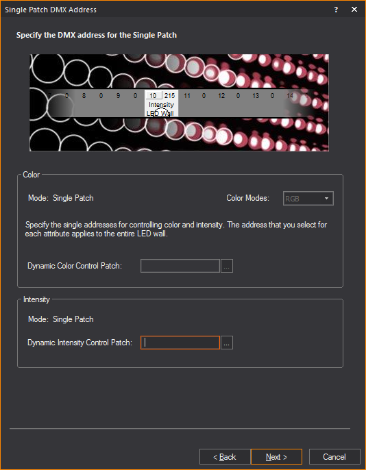
Single Patch DMX Address
This page is displayed if you set Dynamic Color by DMX to the Single Patch
option. If you also set Dynamic Intensity by DMX to
the Single Patch option, it will be active, otherwise it will disabled.
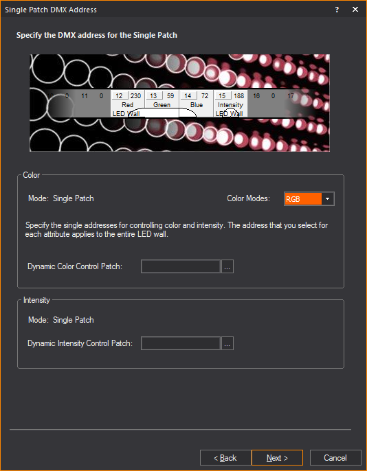
- Select one of several Color Modes by which color
is controlled, enter the DMX control channels for the entire grid,
and then click Next:
- Color Modes:
Choose between RGB, RGBA, RGBW and RGBAW, depending on the device
you are simulating. “RGB” stands for “Red, Green, Blue”; “A” stands
for “Amber”; “W” stands for “White”. The Color Mode setting defines
the number of DMX channels required to control the color mix for
this entire grid.
Note: WYSIWYG
does not actually show white or amber LEDs in its simulation. The additional
“A” and/or “W” channels are offered so this Wizard can account for these
channels in the patch, if necessary.
- Dynamic Color Control
Patch: Type the universe and starting channel number for
this patch, in the format Universe_Name.DMX_Channel_Number. (If
the Universe_Name you typed does not exist, you will be asked
if you wish to create it when you click Next.)
Alternately, you may click the ellipsis button to manually select
a previously-created universe (or create a new one), and then
type the channel number.
Tip: Once
you have finished creating this grid and have inserted it, switch to DATA
mode > Patch view, and click the universe to which you patched it,
in order to verify that the patch has been applied correctly. For example,
if you chose the RGBAW color mode, this grid should span five DMX channels,
starting with the channel number you defined. (For more information on
using the Patch view in DATA mode, see Working
in the patch view.)
- (If active) Dynamic
Intensity Control Patch: Type the universe and channel
number for this patch, in the format Universe_Name.DMX_Channel_Number.
(If the Universe_Name you typed does not exist, you will be asked
if you wish to create it when you click Next.) Alternately, you
may click the ellipsis button to manually select a previously-created
universe (or create a new one), and then type the channel number.
- Click Next.
Result: The
Finished page appears.
- Proceed to step 14.
Single Patch DMX Address with Single Color, Image or Video
Source
This page is displayed if you set “Dynamic
Intensity by DMX” to the Single Patch option, and color is controlled
by Single Color, Image Source or Video Source.
- Enter the address of the (single) DMX channel
used to control the intensity of this entire grid, then click Next:
- Dynamic Intensity
Control Patch: Type the universe name and channel number
for this patch, in the format Universe_Name.DMX_Channel_Number.
(If the Universe_Name you typed does not exist, you will be asked
if you wish to create it when you click Next.) Alternately, you
may click the ellipsis button to manually select a previously-created
universe (or create a new one) and type the channel number.
- Click Next.
Result: The
Finished page appears.
- Proceed to step 14.
Multi Patch and/or Single Patch DMX Address
This page is displayed if you set Dynamic Color by DMX to the Multi Patch
option. Then, depending on the choice for Dynamic
Intensity by DMX, it will be in Single Patch mode or Multi Patch
mode accordingly.
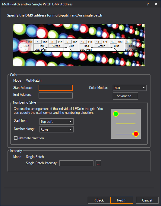
- In the Color section,
enter the DMX address at which the “first” LED in the grid is to be
patched, define which LED in the grid is “first” and how the rest
of the LEDs “follow”, select one of several Color Modes by which color
is controlled (for the entire grid), and then click Next.
- Start Address:
Type the universe and channel number for the first LED in the
grid, in the format Universe_Name.DMX_Channel_Number. (If the
Universe_Name you typed does not exist, you will be asked if you
wish to create it when you click Next.)
The channel numbers for the rest of the LEDs in this grid will
be “calculated” automatically by the LED Wizard, and the last
channel number (and universe) will be displayed in the End Address
field.
Note: In cases
where the number of DMX channels required to patch the grid in this manner
exceed 512 (i.e., the maximum number of channels in a DMX universe) the
LED Wizard will automatically create new universes that start with the
same name and have a number (starting with “1” and incrementing from there)
appended to the name. For example, if the first LED was patched to universe
‘LED’, but two more universes were needed to patch the grid, the LED Wizard
would create two new universes named ‘LED1’ and ‘LED2’.
- In the Numbering Style subsection,
define which LED in the grid is to be considered “first” using
the Start from drop-down list,
and how the rest of the LEDs are to follow it using the Number along drop-down list. Select
the Alternate direction checkbox
to indicate that the numbering direction should change with every
row or column.
- Color Modes:
Choose between RGB, RGBA, RGBW and RGBAW, depending on the device
you are simulating. “RGB” stands for “Red, Green, Blue”; “A” stands
for “Amber”; “W” stands for “White”. The Color Mode setting defines
the number of DMX channels required to control the color mix for
each LED in this grid.
Note: WYSIWYG
does not actually show white or amber LEDs in its simulation. The additional
“A” and/or “W” channels are offered so this Wizard can account for these
channels in the patch if necessary.
- In the Intensity section, specify the patching
information for intensity.
- Single Patch Intensity:
Type the universe and channel number for this patch, in the format
Universe_Name.DMX_Channel_Number. (If the Universe_Name you typed
does not exist, you will be asked if you wish to create it when
you click Next.) Alternately, you may click the ellipsis button
to manually select a previously-created universe (or create a
new one) and type the channel number.
Note: If the
Intensity mode is set to Multi-Patch, then the following page appears.
In this case, the intensity channel controlling the individual LED will
either be before or after the color channels.
- Intensity Patch:
If the intensity channel should follow the color channels, then
set the drop-down list to After Color.
Otherwise, if the intensity channel is before the color channels,
then set the drop-down list to Before
Color.
Note: For
tips on advanced patching techniques, see Advanced patching.
- Click Next.
Result: The
Finished page appears.
- Proceed to step 14.
Multi Patch and/or Single Patch with Color Set to Single
Patch and Intensity Set to Multi-Patch
This page is displayed if you set Dynamic Color by DMX to the Single Patch
option, and the Dynamic Intensity by DMX is
set to Multi Patch.
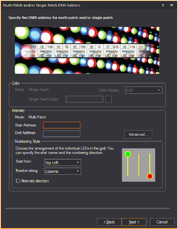
- Enter the DMX address at which the “first” LED
in the grid is to be patched, define which LED in the grid is actually
“first” and how the rest of the LEDs “follow”, then click Next:
- Start Address: Type
the universe and starting channel number for the first LED in
the grid, in the format Universe_Name.DMX_Channel_Number. (If
the Universe_Name you typed does not exist, you will be asked
if you wish to create it when you click Next.) The channel numbers
for the rest of the LEDs in this grid will be “calculated” automatically
by the LED Wizard, and the last channel number (and universe)
will be displayed in the End Address field.
Note: In cases
where the number of DMX channels required to patch the grid in this manner
exceed 512 (i.e., the maximum number of channels in a DMX universe) the
LED Wizard will automatically create new universes that start with the
same name and have a number (starting with “1” and incrementing from there)
appended to the name. For example, if the first LED was patched to universe
‘LED’, but two more universes were needed to patch the grid, the LED Wizard
would create two new universes named ‘LED1’ and ‘LED2’.
- In the Numbering Style subsection,
define which LED in the grid is to be considered “first” using
the Start from drop-down list,
and how the rest of the LEDs are to follow it using the Number along drop-down list. Select
the Alternate direction checkbox
to indicate that the numbering direction should change with every
row or column.
Note: For
tips on advanced patching techniques, see Advanced patching.
- Click Next.
Result: The
Finished page appears.
- Proceed to step 14.
- Click Finish.
Result: The
LED grid attaches to your cursor.
- Click to place the grid into your drawing at the
desired location, or type in the coordinates at which to place it.
Result: The
LED grid is placed into the drawing.
Modify LED Wall
This option displays the LED Wizard again,
and the properties of the selected LED Wall can be modified. Right-click
on the LED Wall and select Modify LED Wall.
Note: This
option is limited to a single LED Wall object at a time.
Advanced patching
This option offers more control in defining
your LED grid’s patching information. By using Auto Insert, each universe
will start at channel 1 and then automatically create all the universes
required to control your LED grid for you. You then have the option to
select a row and edit the start and end channels for each universe if
you wish to do so. Otherwise, you can manually create each universe and
specify start and end channels for each.
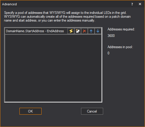
Notes:
- Before typing addresses, consult the figures
shown under Addresses required and
Addresses in pool for an up-to-date
listing of the number that you will need for your grid and the number
that you have already provided.
- Create the patch domain in the address pool box,
following the format DomainName.StartAddress-EndAddress (for example,
a.1-169).
- You can type multiple patch domains (for example,
a.1-160 and b.1-20).
If you assign more domains than are required, the extra domains are
ignored.
- Use the arrow buttons to adjust the order of
the patches (the order in which they appear is the order in which
they are populated).
- If you require more than 512 addresses (the standard
DMX universe), then you must add additional patch domains to meet
your requirement. The addresses can be split over universes.
Type the addresses
manually
- In the box provided, type the required addresses
in the format DomainName.StartAddress-EndAddress (for example, a.1-169).
- Use the arrow buttons to adjust the order of the
patches (the order in which they appear is the order in which they
are populated).
- Click Next, and
then proceed to the next step.
Use Auto Insert
to create the addresses automatically
- Click the Auto Insert icon
to have WYSIWYG automatically create all the addresses that you need
for the grid. In the resulting Auto Insert window, type the Patch
Domain Prefix (for example, a).
- In the Number of Channels
Per Domain box, accept the default value or type a new
value based on the number of channels that you can control.
- In the Start Address box,
type the start address for the patch domain.
- Click OK to
have WYSIWYG populate the End Address (based on the number of channels
required).
- Click Next, and
then proceed to the next step.
Select the addresses
from a list
- If you do not want to manually type the addresses,
click the New icon, and then click
ellipses button (...).
- To create a new patch domain, click Create
New, and then type the domain in the Domain
Name box (for example, a).
- To choose a patch domain from those that you
have saved with your current WYSIWYG file, click Select
From List, and then highlight the domain name.
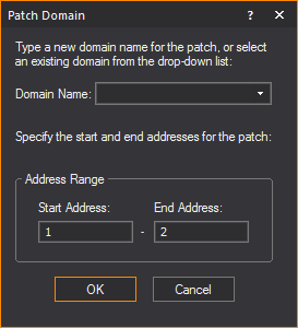
- Type the Start and End addresses for this patch
universe.
- Click OK.
- Click Next, and
then proceed to the next step.
Creating video walls
with LED wall
After an LED wall has been created, the
Grid Array tool can be utilized to build a video wall. Applying Grid Array
opens the Quick Image/Video Tool where you can set the video/image sources
to the screen panels that were created.
To create video walls with led wall
- In Front or
Back view in Wireframe,
select the LED Wall.
- From the menu,
click > .
Result: The
Grid Array window appears.
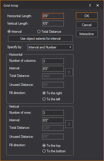
- In the Grid Array window,
modify the settings as desired. Refer to Array
for information on Grid Array settings.
- Click OK.
Result: The
Quick Image/Video Tool appears.
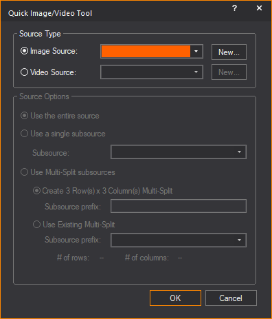
- In the Quick Image/Video
Tool window,
- Specify the video or image sources and subsources
for the video wall that was created.
- Apply existing subsources or create new subsources
that will match the row and columns of the video wall.
- Click OK.
Result: The
video wall is created with the video or image applied to the individual
LED walls.
Notes:
- The Quick Image/Video
Tool can be applied to previously drawn LED Wall files,
if re-arranged into rows and columns that WYSIWYG can recognize and
automatically apply subsources to the individual LED Walls.
- The Quick Image/Video
Tool can be applied to missing panels in the video wall,
if WYSIWYG can recognize the arrangement of rows and columns.
- The functionality of the Quick
Image/Video Tool remains available if no screens are selected.
LED wall properties
After an LED Wall has been created, the
properties of the LED Wall can be altered from the Properties window.
Note: Multiple
LED Wall objects can be selected and their properties edited all at once,
if all specifications of the selected LED Walls
are identical.
The following properties of the LED Wall
can be changed:
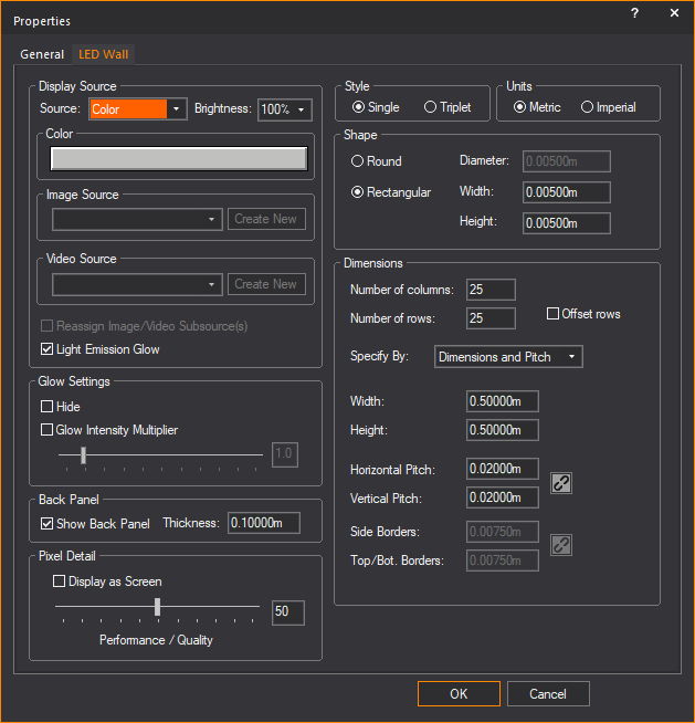
In the Display
Source section, change the content and display properties.
- Source: Change
what this LED Wall displays by selecting from the source drop-down
list.
- Brightness: Change
the brightness level by selecting from the percentage drop-down list.
- Color: If Color
is the selected source, click this color box to change the color.
- Image Source: If
Image Source is the selected source, select from the drop-down list
or click Create New, browse and select
the new image file.
- Video Source: If
Video Source is the selected source, select from the drop-down list
or click Create New, browse and select
the new video file.
- Reassign Video/Image Subsource(s):
This checkbox is available when the LED Wall is set with Multi-split
subsources. Select this checkbox to open the Reassign
Video/Image Subsource dialog box and reassign the video
and image source types and options for the LED Wall.
- Light
Emission Glow: Select this checkbox to display in Shaded view
the light emission glow effect from the LED array.
Clear this checkbox if you do not want
to display the light emission glow effect.
By default, Light
Emission Glow is enabled for the LED Wall. Ensure that Glow is enabled in the Light
Emission section of the Visual Effects tab
in View Options window in Shaded view.
In the Glow Settings section,
you can adjust the intensity of the glow from the LED Wall.
Notes:
- In Shaded view, the Screen/LED
Wall Glow settings in the Simulation tab
of the View Options window must be
enabled to see the glow from the LED wall lighting up an object. See
Simulation
tab.
- The Light Emission Glow effect is not passed
on to the Renderer when you use the Render
Wizard to render the Shaded view.
- Hide: Select this
checkbox to disable access to the Glow Intensity
Multiplier.
- Glow Intensity Multiplier:
Select this checkbox to enable the Glow Intensity
Multiplier slider and use it to adjust the intensity.
In the Back Panel section, change the back panel
settings for the LED Wall.
- Show Back Panel:
Select this checkbox to display the black back panel for the LED Wall.
- Thickness: Type
in the thickness of the back panel.
In the Pixel Detail section,
- Pixel Detail slider:
Use the slider to control the LED Wall quality vs. performance setting.
An increase in pixel detail will result in a decrease in performance.
- Display as Screen:
If the source of your LED wall is color, image or video, select this
checkbox to display the LED wall as a screen with a projected image
instead of a detailed grid of LED pixels forming the image. Display as Screen does not work if the
source of the LED wall is Dynamic DMX patch.
In the Style section,
change the style of the LEDs that were used in the LED Wall.
- Single: Choose
this option to use single LEDs which produce Red, Green and Blue.
- Triplet: Choose
this option to use LED clusters comprised of Red, Green and Blue LEDs.
In the Units section, change the measurement
unit that were used in the LED Wall.
- Metric: Choose
this option to specify the measurements in meters.
- Imperial: Choose
this option to specify the measurements in feet and inches.
In the Shape section,
change the shape of the individual LEDs used in the LED Wall.
- Round: Choose this
option if you want the shape of the Single or Triplet LED to be round.
- Rectangular: Choose
this option if you want the shape of the Single or Triplet LED to
be a rectangle.
In the Dimensions section, change the layout properties
of the LED Wall.
- Number of columns:
Type the number of columns in the grid.
- Number of rows:
Type the number of rows in the grid.
- Offset rows: Select
this checkbox to offset the rows in the grid by one-half of the Horizontal
Pitch.
- Specify By: Change
the parameters that were used in the LED Wall by selecting from the
drop-down list.
- Width: Type the
overall width of the LED Wall.
- Height: Type the
overall height of the LED Wall.
- Horizontal Pitch:
Type the horizontal center-to-center distance between LEDs in the
LED Wall.
- Vertical Pitch:
Type the vertical center-to-center distance between LEDs in the LED
Wall.
- Side Borders: Type
the distance between the left edge of the LED Wall and the edge of
the left-most column of LEDs. The same value will be applied to the
bottom row of LEDs.
- Top/Bot. Borders:
Type the distance between the top edge of the LED Wall and the edge
of the top row of LEDs. The same value will be applied to the bottom
of the device.