Drawing pipes
Pipes are single member hang structures
symbols that are displayed with thickness in 2D CAD Wireframe views and
in associated paperwork views. In isometric views, pipes will be displayed
in line representation. The default thickness of the pipe can be viewed
and changed in the Hang Structure Settings tab
in the Document Options window.
Pipes can be set to be drawn from the center
or from the start. The first pipe drawing mode, Draw
from Start, requires pipes to be drawn by specifying the start
point and the end point (from one extremity of the pipe to the other).
The second pipe drawing mode, Draw
from Center, requires that the pipe be drawn by specifying the
center point and one end point or extremity of the pipe. Although it is
only necessary to enter all points when drawing in interactive mode, the
pipe drawing mode will affect the insertion point of the pipe when drawing
using the pipe dialog box. The drawing mode will also affect how the fixtures
are hung when using pipe snap, how the fixture offset distance is measured,
and how pipe tape prints are labeled.
Note: Only
Pipe objects inserted in the drawing from the Library will be displayed
in Truss Manager. Pipes drawn in CAD Wireframe
will not be displayed in Truss Manager.
To set the pipe drawing mode
- From the menu,
choose .
- Click the Hang Structure
Settings tab.
- In the Pipe Drawing Mode section,
select Draw from Center or Draw from Start.
Tips:
- You can change the default setting for a pipe
in mid-command by right-clicking and choosing the drawing mode for
that pipe just before inserting it into the drawing.
- You can change the pipe mode for a specific pipe
at any time in the pipe’s properties. For more information, see Pipe
properties.
To draw a pipe
- From the menu,
choose .
 The
Pipe button.
The
Pipe button.
Result: The
New Pipe dialog box appears.
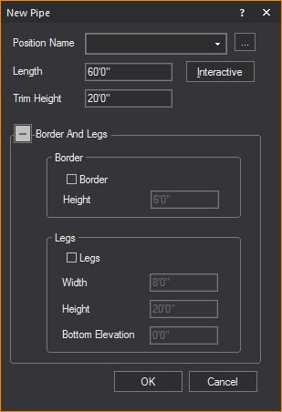
- In the New Pipe dialog
box, find the name of the pipe. If you need to create the name of
the pipe, click the ellipsis button [...] to open the Position Manager.
Click New, and then type the name of
the pipe.
- In the Length box,
type the length of the pipe, if different from the default. The default
value is 60’0”.
- In the Trim Height box,
type the desired trim height for the pipe. The default value is 20’0”.
Note: Pipes
ignore the missing coordinate setting when drawn using this method.
- To add a border to the pipe, under the Border
And Legs section, in the Border subsection, select the Border
checkbox.
- Enter the height of the border in the Height
field.
- To add legs to the pipe, in the Legs subsection,
select the Legs checkbox.
- Enter the width of the legs in the Width
field.
- Enter the height of the legs in the Height
field.
- Enter the bottom elevation of the legs in the
Bottom Elevation field.
- Click OK.
Tip: You may
also use the Pipe tool on the Draw toolbar.
To draw a pipe from center in interactive mode
- From the menu,
choose .
 The
Pipe button.
The
Pipe button.
Result: The
New Pipe dialog box appears.
- In the New Pipe dialog
box, click Interactive.
- Set the height of the pipe that you are about
to draw by pressing the TAB key,
and then entering a value for the missing coordinate, if applicable.
- Right-click and select .
- Click to place the center point of the pipe.
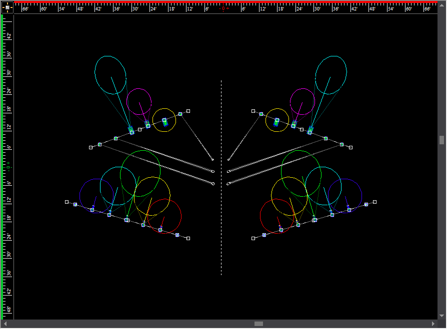
- Drag it to the proper length, and then click to
place the end point of the pipe. Notice that the pipe extends in both
directions - mirrored at center.
- Right-click on the pipe that you have just drawn,
and then click .
- Click the Hang Structure
tab.
- From the Name drop-down
list, select the name for this new pipe. If the name is not already
in the list, use the Position Manager [...]
to enter the new name.
- Repeat to draw more pipes.
To draw a pipe from start in interactive mode
- From the menu,
choose .
 The
Pipe button.
The
Pipe button.
Result: The
New Pipe dialog box appears.
- In the New Pipe dialog
box, click Interactive.
- Set the height of the pipe that you are about
to draw by pressing the TAB key,
and then entering a value for the missing coordinate, if applicable.
- Right-click and select .
- Click to place the starting point of the pipe.
- Drag it to the proper length, and then click to
place the end point of the pipe. Notice that the pipe extends in one
direction.
- Right-click on the pipe that you have just drawn,
and then click .
- Click the Hang Structure
tab.
- From the Name drop-down
list, select the name for this new pipe. If the name is not already
in the list, use the Position Manager [...]
to enter the new name.
- Repeat to draw more pipes.
Drawing curved pipes
In addition to drawing pipes linear in
shape, pipes may be drawn curved in arcs.
To draw a curved pipe
- From the menu,
choose .
 The Curved Pipe button.
Result: The
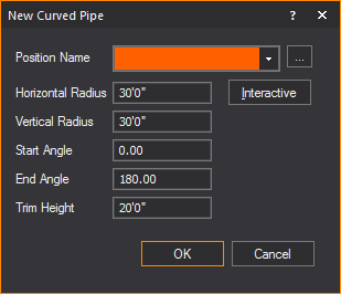
New Curved Pipe dialog box appears.
- In the New Curved Pipe dialog
box, find the name of the pipe. If you need to create the name of
the pipe, click the ellipsis button [...]
to open the Position Manager. Click
New, and then type the name of the
pipe.
- In the Horizontal Radius field,
type how long the pipe radius will be horizontally, if different from
the default. The default value is 30’0”.
- In the Vertical Radius field,
type how long the pipe radius will be vertically, if different from
the default. The default value is 30’0”.
- In the Start Angle field,
type what angle the pipe orientation will start at, if different from
the default. The default value is 0°.
- In the End Angle field,
type what angle the pipe orientation will end at, if different from
the default. The default value is 180°.
- In the Trim Height box,
type the desired trim height for the pipe. The default value is 20’0”.
Note: Pipes
ignore the missing coordinate setting when drawn using this method.
- Click OK.
To draw a curved pipe from center in interactive mode
- From the menu,
choose .
 The
Curved Pipe button.
The
Curved Pipe button.
Result: The
New Curved Pipe dialog box appears.
- In the New Pipe dialog
box, click Interactive.
- Set the height of the pipe that you are about
to draw by pressing the TAB key,
and then entering a value for the missing coordinate, if applicable.
- Right-click and select .
- Click to place the first point of the horizontal
axis.
- Click to place the second point of the horizontal
axis.
- Click to set the vertical radius.
- Click to place the center point of the pipe.
- Drag it to the proper length, and then click to
place the mid point of the pipe.
- Click to place the start point of the pipe. Notice
that the pipe extends in both directions - mirrored at center.
- Right-click on the pipe that you have just drawn,
and then click .
- Click the Hang Structure
tab.
- From the Position Name drop-down
list, select the name for this new pipe. If the name is not already
in the list, use the Position Manager [...]
to enter the new name.
- Repeat to draw more pipes.
To draw a curved pipe from start in interactive mode
- From the menu,
choose .
 The
Curved Pipe button.
The
Curved Pipe button.
Result: The
New Curved Pipe dialog box appears.
- In the New Pipe dialog
box, click Interactive.
- Set the height of the pipe that you are about
to draw by pressing the TAB key,
and then entering a value for the missing coordinate, if applicable.
- Right-click and select .
- Click to place the first point of the horizontal
axis.
- Click to place the second point of the horizontal
axis.
- Click to set the vertical radius.
- Click to place the center point of the pipe.
- Drag it to the proper length, and then click to
place the mid point of the pipe.
- Click to place the start point of the pipe. Notice
that the pipe extends in both directions - mirrored at center.
- Right-click on the pipe that you have just drawn,
and then click .
- Click the Hang Structure
tab.
- From the Position Name drop-down
list, select the name for this new pipe. If the name is not already
in the list, use the Position Manager [...]
to enter the new name.
- Repeat to draw more pipes.
Mirroring pipes
Once a pipe is created, a mirror image
of the pipe can be created. Mirroring duplicates and reverses the pipe,
inserting it the same distance from an axis line as the original pipe.
Both straight and curved pipes can be mirrored. A mirrored pipe will also
include any fixtures attached to the original pipe, but aiming the fixtures
at the new mirrored angle. For more information, see Mirroring.
Pipe
properties
Options on the Pipe tab
affect the mode, offset, and dimensions of a pipe.
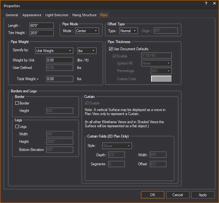
- Length: Type new
text to change the length of the selected pipe.
- Trim Height: Type
new text to change the trim height. If the pipe is vertical, this
value determines the lowest Z value of the pipe.
Pipe Mode
- Mode: Select the
pipe mode for the specific pipe from the drop-down list.
- Start: If
enabled, pipes are drawn from one end to the other. When start
mode is used, offset is measured from the beginning of the pipe
in a positive direction.
- Centre: If
enabled, pipes are drawn from the center out to both ends at the
same time. When center mode is used, offset values are either
positive or negative, measured from the center of the pipe.
Offset Type
- Type: Offset is
a fixture property that measures where a fixture is hung on a pipe.
The value depends on the pipe mode selected.
Pipes can also base the Offset on a specified
coordinate. In this case, a fixture’s offset value is calculated as the
distance on the specified axis from the specified coordinate. This is
handy if you have many small pipes grouped together to form one hang position,
for example the Balcony Rail. If this is the case, choose all the pipes’
properties to have their Offset based about X=0. Fixtures on the Balcony
Rail will then report where they are relative to the theatre, rather than
the beginning of the pipe.
This offset methodology can be extended
to box booms as well. For example, a boom in the first box (which is 10’
above the deck) can be drawn as a vertical pipe and have its offset to
be based about Z=10’. A fixture’s offset will then tell you how high (from
the bottom of the box) to hang it.
In WYSIWYG, set the offset mode that you
want to use. The choices are:
- Normal, which
indicates that the offset is based on the pipe mode.
- X, Y, and
Z, which calculates the offset
based on the specified coordinate.
If you have selected an X, Y, or Z offset
type, then you must specify a coordinate on the axis from which offset
values will be calculated.
Pipe Weight
- Specify by: Select
how to specify the weight value.
- Weight by Unit:
Type a weight value equivalent to a unit of measurement.
- User Defined:
Type a custom weight value for the selected pipe object.
- Total Weight:
Displays the sum total weight for the selected pipe object.
Pipe Thickness
- Use Document Defaults:
Select this checkbox to reference the options selected on the Wireframe Details tab in Document
Options. Clear the checkbox
to make specific changes for the active view.
- Enable: Select
this checkbox to display the selected pipe with thickness in 2D CAD
Wireframe views and in associated paperwork views (Not in isometric
views).
- The box displays the default thickness of the
pipe. Type a new value to change the default thickness.
- Symbol Fill: Select
the fill option None, or Percentage or
Custom Color from this drop-down
list.
- Percentage: Set
the percentage from the drop-down list for the hue intensity of the
fill.
- Custom Color:
Click the color select box and select the custom color as the fill.
Border and Legs
- Border: Select
this checkbox to change the Height
of the added border.
- Legs: Select this
checkbox to change the Width, Height and Bottom
Elevation of the added legs.
Curtain
- Enable: Select
this checkbox to add a curtain to the pipe.
- Style: Select
from this drop-down list to change the pattern of the curtain.
- Depth: Type a
new value to change the depth of the curtain pattern.
- Width: Type a
new value to change the width of the curtain pattern.
- Segments: Type
a new value to change the number of segments in the curtain pattern.
- Offset: Type a
new value to change the distance measurement value between curtain
and pipe.