DWG/DXF files
In this section
Importing_DWG/DXF
Merging DWG/DXF
Exporting
DWG/DXF
Importing DWG/DXF
When importing a DWG/DXF file into WYSIWYG,
you have two options:
- You can open
a DWG/DXF file.
- You can merge a
DWG/DXF file into an existing WYSIWYG document.
If you open a DWG or DXF file while another
show document is currently open, you are prompted to save changes to that
document before another show document is opened. Only one show document
may be open at a time. When you merge documents, it enables you to add
the contents of the DWG or DXF file to the contents of the current document.
3D solids contained within an AutoCAD file
are automatically placed inside blocks by AutoCAD. When you import any
file that contains a block, WYSIWYG will automatically explode the blocks
in the DXF or DWG files for you if you decide to do this before opening
them in WYSIWYG.
Note: WYSIWYG
supports DWG or DXF files from AutoCAD version 2018 format and earlier
at the time of this release.
Entities
that can be imported
The DWG/DXF entities that can be imported
are detailed in the following table. The resulting WYSIWYG objects are
also shown.
DWG/DXF
entity |
WYSIWYG
object |
Circle |
Circle |
Point |
Point |
Arc |
Arc |
Line |
Line |
Leader |
Line and Text |
MLeader |
Line and Text |
Ellipse |
Circle or line* |
2D Polyline |
Line |
3D Polyline |
Line |
Mline |
Line |
Spline (see Note) |
Spline or Line |
Text |
Text |
MText |
Group of text items |
Polyface Mesh (PFACE) |
Set piece |
Polygon Mesh (3D Surfaces) |
Set piece |
Face (3D Face) |
Surface |
Aligned dimension |
Dimension |
Rotated dimension |
Dimension |
Region |
Surface |
Cylinder |
Cylinder |
Sphere |
Sphere |
Cone |
Cone |
Box |
Riser |
Planar Surface |
Surface |
Revolved Surface |
Set Piece |
Helix |
Line |
Lines with bulges |
Lines and Arcs |
Attribute
Text |
Text
Label (with attributes substituted) |
* A closed AutoCAD ellipse will be imported
as a circle; otherwise, it is imported as a multi-segment line.
Entities
that can be imported as a library item
- Circle
- Arc
- Line
- 2D Polyline
- 3D Polyline
- Polyline
- Mline
- Polyface Mesh (PFACE)
- Polygon Mesh (3D Surfaces)
- Face (3D Face)
- Spline
- Ellipse
- Revolved Surface
- Helix
- Text and MText (See Note)
Note: Text
and MText entities in blocks are not integrated directly into library
items (a feature WYSIWYG does not support). However, a copy of each Text
or MText entity is extracted from the block and inserted into WYSIWYG
document as a text label. Attributes are substituted.
Limitations
- Multilines becomes single lines.
- Multiline text becomes a group of individual text
items, with each line represented by its own item.
Note: The
formatting for each line is taken from that of the first character of
the line, except in the case of bullets, in which case the first character
after the bullet point is used.
- Segments that are not straight (for example, arcs)
become straight line segments.
- A spline must contain “Fit” data for it to be
imported. When a Spline is initially drawn in AutoCAD, it is defined
by a series of user-provided Fit Points, which are automatically converted
to Control Points by AutoCAD. To import Splines into WYSIWYG properly,
you must maintain the Fit Points that define the Spline. If the Spline
is defined only by Control Points, it will import into WYSIWYG as
a regular line, with additional points to help follow the curvature.
- Stretched (scaled) blocks are not supported.
- Blocks to be converted to library items cannot
imbed other blocks.
- Blocks to be replaced by a fixture cannot imbed
other blocks.
Tips:
- Do not import 2D/3D solids whenever possible.
Instead, use 3D Face and 3D Surface entities.
- It is recommended that you explode Polyface Mesh
or Polygon Mesh entities in AutoCAD before importing to WYSIWYG so
you can access each face in WYSIWYG.
Opening
a dwg/dxf document
Before you begin
Clean up the CAD file by removing all unnecessary
layers, such as doors, windows, and architectural details. Generally you
want to remove items that you do not need to see or will not use in the
plot.
Use the Purge command in AutoCAD to remove
layers, blocks, and so on, that are not wanted or needed. You may want
to do this several times since layers and blocks are sometimes linked
to other parts of the drawing, and the Purge command might not pick them
up the first time. The more unwanted items you can remove, the smaller
the file size will be, and the easier/faster it is to import.
To open a dwg/dxf document
This procedure creates a new WYSIWYG document
from the imported DWG/DXF file. If you are already working in a document,
you are prompted to save any changes and close the document before you
import the file into WYSIWYG.
- From the menu,
choose .
- From the files of type box, select the DWG or
DXF type. Files of this type appear in the browser window.
- In the browser, click the file name, and then
click Open.
Result: The
Pre-Processing Options window appears.
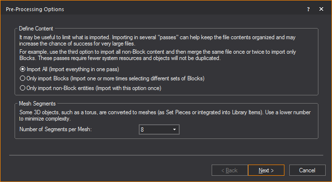
- In the Pre-Processing
Options window, you can specify which DWG/DXF blocks and
non-block entities are converted into Library items.
- From the Define Content
section, choose which layers and items will be converted into
your drawing.
- Select the Import
All radio button to include in the import, all blocks,
block references, all non-block items and layers for conversion
into your drawing. You can import all entities in one pass if
you select this option.
- Select the Only import
Blocks radio button to include in the import, only
items that are blocks and block references for conversion into
your drawing. You can import one or more times selecting different
sets of blocks if you select this option.
- Select the Only import
non-block entities to exclude from the import, all
items that are blocks and block references. You can import only
once if you select this option.
- From the Number of Segments
per Mesh drop-down list in the Mesh
Segments section, choose the number of segments that will
affect how the Library Items and Set Pieces are converted into your
drawing. Blocks with higher number of segments consume more memory
which affect the performance of your computer hardware.
- Click Next.
Result: The
Working dialog box appears showing
the Pre-processing progress bar, and
then the Scale window appears.
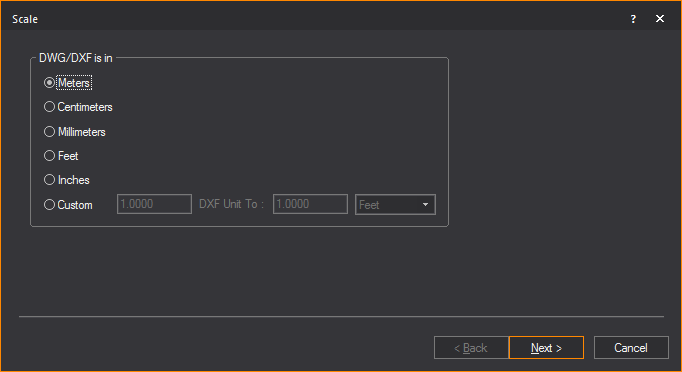
- Select the unit type used in the DWG/DXF drawing.
- Click Next.
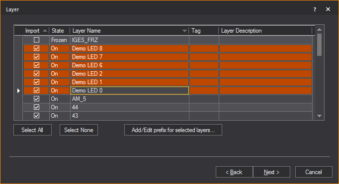
Result: The
Layer window appears.
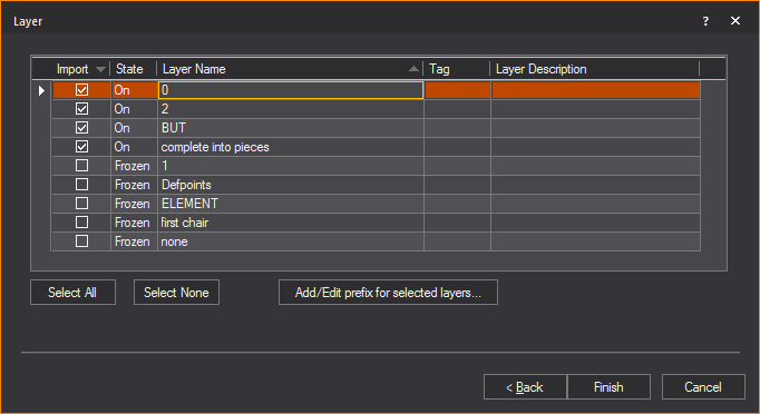
- Highlight the layers that you want to import.
Note that you do not need to import all the layers at once. Refer
to Importing
scenario for suggestions on how to import the various
layers. For each layer that you want to import, ensure that the Import checkbox is checked. If you do
not want to import a certain layer, highlight it and clear this checkbox.
Note: In the
Layer window, the State column shows
the state of the layer in the DWG/DXF file. Frozen layers are not selected
for import by default. Off layers are selected but will be set to Not
Visible in WYSIWYG after import.
- To add a description to the layer, enter the information
in the Layer Description field of the
layer.
- To add metadata to the layer, enter in a descriptive
tag in the Tag field of the layer.
- To add a prefix to selected layers, click Add/Edit prefix for selected layers... button.
Result: The
Change Layer Prefix dialog box appears.
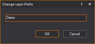
- In the Change Layer Prefix dialog
box, enter in the desired prefix you want to add to the selected layers.
- Click OK.
Result: The
selected layers have the prefix added to the layer’s name.
Note: If a
prefix is added to a layer that previously had a prefix assigned, the
new prefix will override the old prefix.
- Click Next.
Result: The
Block window appears.
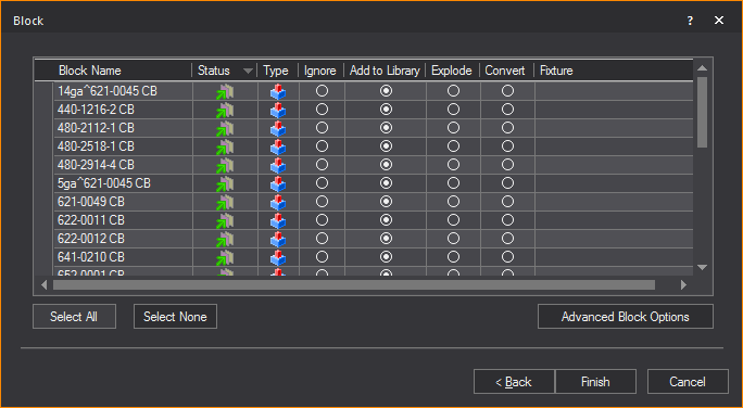
- If you have blocks in your drawing, you have the
option to ignore the blocks, explode the blocks, convert them into
a library item, or substitute WYSIWYG fixtures for the existing blocks.
Note: 3D solids
are automatically placed inside blocks by AutoCAD, and assigned an abstract
block name (for example, *X1). The number of “blocks” that are found are
dependent on the number of solids that were in the AutoCAD file. You will
be prompted to determine what action to take for each type of “block.”
- Block Name: The
name of the block.
- Status: This icon
 indicates that the
block is currently on a layer being imported. This icon
indicates that the
block is currently on a layer being imported. This icon  indicates that the block
is on a layer that will not
be imported.
indicates that the block
is on a layer that will not
be imported.
- Type: This icon
 indicates that the
block is a singular block and does not contain any sub-blocks. This
icon
indicates that the
block is a singular block and does not contain any sub-blocks. This
icon  indicates
that the block is a nested block and contains one or many sub-blocks.
indicates
that the block is a nested block and contains one or many sub-blocks.
- Ignore: Select
this action to ignore the block. The block will not be added to the
resulting file.
- Add to Library:
Converting a block into a library item imports the object and creates
a duplicate of it to add to the library for future use. Note that
the component will lose all surface properties, such as color and
texture, and it will only be available in the library of the current
document. To make it available globally, see To create
a custom library item. When you convert DWG or DXF files
into custom library items, they appear on the Library tab
of the Library Browser within
the DWG or DXF folder.
- Explode: Exploding
the component breaks it into its sub-components. That is, it breaks
the block into its components. You must be careful of components that
are made up of other components as WYSIWYG will only explode down
one level.
Note: Exploding
is not recommended. Exploding should be your last resort to import the
file, as it is taxing on performance.
- Convert: Converting
a component into a fixture replaces the DWG/DXF component with a WYSIWYG
fixture of your choice. Once you have selected this option, select
the ellipsis in the neighboring column.
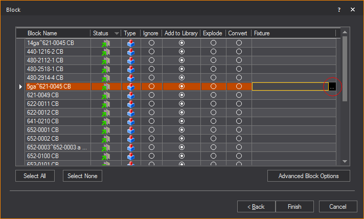
Result: The
Library Browser window appears.
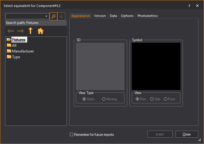
- Select the fixture that you want to use to replace
the block. If you find that you are always replacing a particular
type of component with a specific fixture, you can set an option in
WYSIWYG so that the substitution will automatically occur each time
you import the component. For example, if you have files in which
the ‘PAR64M’ block is always a PAR 64 fixture with an MFL bulb, you
have the option of telling WYSIWYG to automatically import the component
in that way. To change this option, edit the Import.lst file that
is created in the Library folder (usually C:\Program Data\CAST Software\WYSIWYG\1.xx.xx.x\Library)
once the first fixture is set to be remembered for future imports.
Note: WYSIWYG
creates a pipe for every imported fixture since fixtures in WYSIWYG need
to hang on a hang structure. If, however, fixtures are on a straight pipe
represented by a straight line in the DWG file, WYSIWYG will convert the
entire line into a pipe.
Tip: If you
select the Remember for future imports checkbox
in the Library Browser, WYSIWYG will automatically
map the same fixture that appears again in the next DWG/DXF file being
imported. (You can change the automatic mapping if required.)
- Click Advanced Block Options to
filter objects within the block based on their layer.
Result: The
Advanced Block Options dialog box appears.
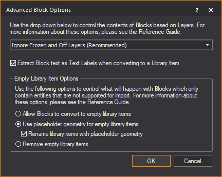
Use the drop-down menu to control how the
contents of incoming Blocks should be handled based on the layers on which
the Blocks’ components reside.
- Ignore Frozen and
Off Layers (Recommended): This is the preferred option
in most cases, since it offers the best optimization for the import:
no parts of Blocks that are on layers which have been turned Off
and/or Frozen will be imported. Once the import is complete, what
you see will most-closely match what is seen when this file is
opened in AutoCAD or DWG TrueView—with the exception of DWG entities
that cannot be imported at this time. (Use the radio buttons in
the Empty Library Item Options section to control how to deal
with such entities.)
- Ignore Only Frozen
Layers: Choosing not to import parts of Blocks that are
on layers which have been Frozen will skip those parts, but parts
that are on layers which have been turned Off will import. This
will lead to a potentially more complete, but also more complex
model—but entities that cannot be imported at this time will still
not import. It is important to remember that if you chose to convert
such Blocks to DWG Library Items, you will have no control over
them: you will not be able to “edit” the DWG Library Item in order
to “remove” from it the parts which were imported from the layers
that were Turned Off.
- Ignore All Layers
Not Being Imported: This option offers layer-based control
over which parts of a Block should be ignored for import: entities
which exist on layers that you have chosen not to import (in the
previous step of the DWG/DXF Import Wizard) will not import. It
is recommended that you only select this option if you are very
familiar with the contents of the file you are importing AND when
you are performing a “multi-pass” import (i.e. importing the same
file multiple times, with different options and/or with only handful
layers at a time).
- Import Everything
(All Layers): This option should only be used when the
previous options fail to yield the desired import result, and
should (ideally) only be chosen when a single Block, or only a
handful of Blocks, are selected for import; while it will lead
to a complete import (with the exception of DWG entities that
cannot be imported at this time), the resulting model (DWG Library
Item) may look altogether different than what you see when you
open the file in AutoCAD or DWG TrueView. In addition, the model
may end up being very complex, which can lead to performance issues.
Use this option with caution, and, ideally, only when performing
a “multi-pass” import.
- Extract Block text
as Text Labels when converting to a Library Item: Since
WYSIWYG’s Library Items cannot contain text, Text or MText objects
contained within Blocks being imported would have to be discarded;
select this option (recommended) in order to extract text from
such Blocks and add it to the resulting .wyg file as a Text Label
object.
- Empty Library Item
Options: Use the radio buttons in this section to control
what will happen with Blocks which only contain entities that
cannot be imported, if you choose to convert them to DWG Library
Items; these options will not affect DWG Blocks that you have
chosen to Explode.
- Allow Blocks to convert
to empty Library Items: This option will allow such blocks
to convert into empty/”zero-length” DWG Library Items. You will
not be able to select them, and inserting them will result in
a non-selectable item. Not recommended.
- Use placeholder geometry
for empty library items: This option (recommended) will
replace entities contained in such Blocks with a 1m “Spike” DWG
Library Item.
- Rename library items
with placeholder geometry: Enable this checkbox to add
a “PH” prefix to all such DWG Library Items.
- Remove empty library
items: When this option is selected, all such Blocks will
be ignored: no empty Library Items will be created, but at the
same time, there will be no indication whatsoever that something
was supposed to be there. Only select this option if you are sure
that you do not require that information.
- Click OK to
apply the set options and close the Advanced
Block Options dialog box.
- Click Finish.
Result: The
Import Summary window appears.
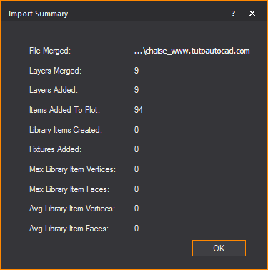
- Click OK.
The CAD importing guide
For more detailed information about importing
DWG/DXF files, please read through the CAD Importing Guide, at http://cast-soft.com/wysiwyg/cad-importing-guide/.
Merging
a dwg/dxf document
To
merge a dwg/dxf document
This procedure inserts the imported DWG/DXF
file into an existing WYSIWYG document in the location of your choice.
At a certain point, the merging procedure
is the same as the opening procedure until the end where you choose where
to place the object you are merging.
- From the menu,
choose .
Result: The
Merge dialog box appears.
- In the Merge dialog
box, beside the File name box, select DWG
or DXF Files (*.dwg or .dxf) from the drop-down list.
- Locate the location of the DWG file on your computer.
Select the file and click Open.
Result: The
Merge dialog box appears asking for a Base
point.
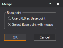
- Select the radio next to the desired Base point.
- Click OK.
- Follow the procedure Steps
3 to 15 of the To open a dwg/dxf document section.
At this point, the steps are the same as with opening until the end
when you choose where to place the object you are merging.
Result: The
Merge Summary window appears.
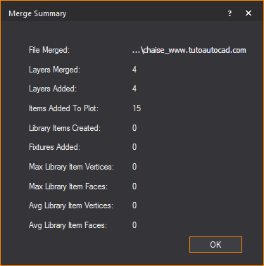
- Click OK.
- If you chose Select Basepoint
with mouse in Step 4, click to place the object in the
drawing.
The CAD importing guide
For more detailed information about importing
DWG/DXF files, please read through the CAD Importing Guide, at http://cast-soft.com/wysiwyg/cad-importing-guide/.
Importing
scenario
You do not need to import everything in
your file at once. You can import items one by one or separately to ensure
accuracy. The following scenario may help you when importing DWG/DXF files
into WYSIWYG:
- After choosing to open a DWG/DXF file, switch
to the Layers tab in the Select DWG Settings
dialog box. In this tab, you can clear the layers that you
do not want imported in the first round. For example, you may only
want to import the venue and all the layers related to it. In the
case of a 2D CAD drawing, it is easier to extrude lines into walls
and do everything else needed to complete the virtual venue. It will
also be quicker as WYSIWYG will have a lot less objects with which
to work.
- Once you have completed working on the venue,
you may want to merge in the hang structures if they exist in the
CAD file. Using the command
from the menu, you can open
the same CAD file once again, and choose the appropriate layer(s)
from the Layers tab. When WYSIWYG
asks you to pick the insertion point, make sure you select Use
0,0,0 as Basepoint. This will ensure that everything in the
new layer is placed accurately in the WYSIWYG plot.
- Continue in the same manner with fixtures and
the other objects. Note that if in the CAD file the fixtures exist
on different layers, you may want to bring these in separately/one
by one as well.
Exporting
DWG/DXF
If you need to send your WYSIWYG drawings
to someone using another drafting program, you can export your file to
the DWG or DXF file type. DWG and DXF formats are used to transfer documents
to AutoCAD or other compatible drafting applications.
Entities that can be exported
- 2D DWG/DXF:
When you export WYSIWYG objects to a 2D
DWG/DXF file, all objects, including fixture attributes, are converted
to lines.
- 3D DWG/DXF:
The objects that can be exported to a 3D DWG/DXF
file and the resulting DWG/DXF entities are shown in the following
table. Fixture attributes cannot be exported to 3D DWG/DXF.
WYSIWYG
object |
DWG/DXF
entity |
Line |
3D Polyline |
Spline |
Spline |
Point |
Point |
Circle |
Circle |
Arc |
Arc |
Text |
Text |
Pipe |
Line |
Rigging Point (3D) |
Block - line, circle, text |
Dimension |
Lines and MText |
Callout |
Leader |
All
other objects |
PolyFace
Mesh |
Note: You
cannot export truss.
Limitation
The slope near the end of two lines may
be slightly off.
To export to dwg/dxf in 2D
Note: When
you export WYSIWYG objects to a 2D DWG/DXF
file, all objects, including fixture attributes, are converted to lines.
- From the menu,
choose .
Result: The
Export browser window appears.
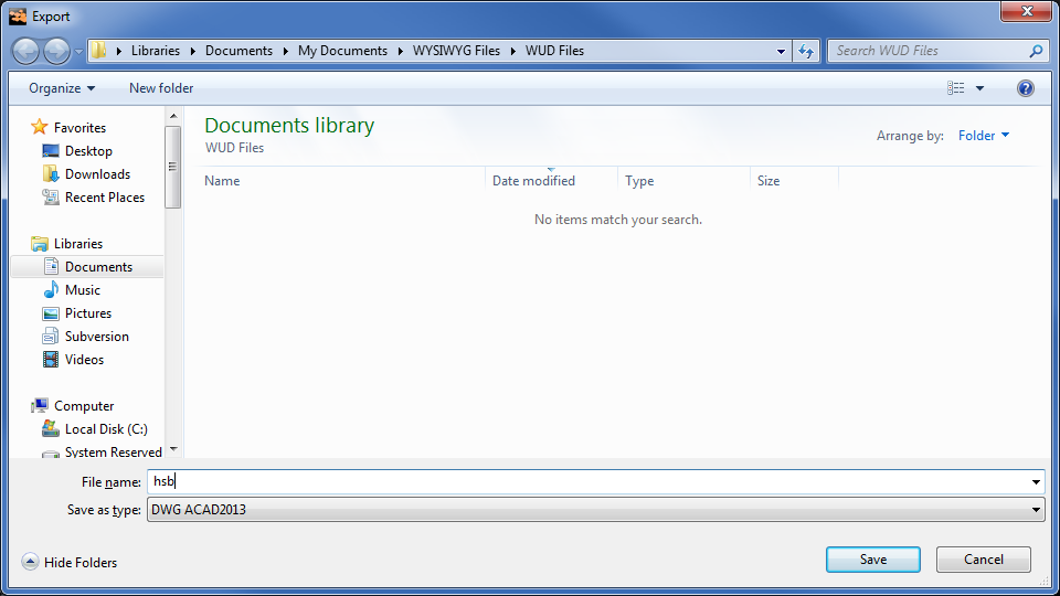
- In the Export window,
navigate to the location where you want to save the exported file.
Ensure that the destination appears in the Save
in drop-down list.
- In the File name box,
type the name of the exported file.
- From the Save as type
drop-down list, choose the exported file type. There are a
number of choices available for file type, based on AutoCAD versions.
- Click Save.
Result: The
Select DXF/DWG Settings For Export dialog
box appears.
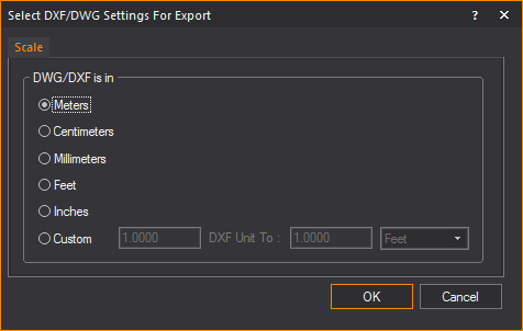
- On the Scale tab,
click the option button for the units to be used in the DWG/DXF drawing.
- To specify a custom unit of measurement, select
the Custom option button.
- In the DXF Unit To boxes,
specify the mapping of the units of measurement to use in the exported
file.
- Click OK.
Note: The
current type of the drawing will be used as the point of view in the exported
2D drawing.
To export to dwg/dxf in 3D
Note: When
you export WYSIWYG objects to a 3D DWG/DXF
file, the resulting DWG/DXG entities vary. For details, see the table
on Exporting
dwg/dxf files.
- From the menu,
choose .
Result: The
Export browser window appears.
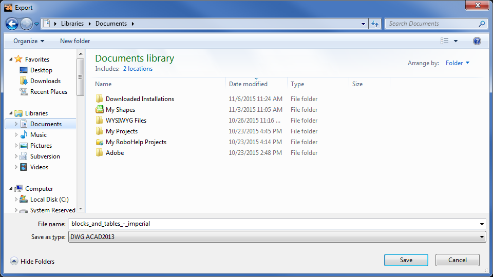
- In the Export window,
navigate to the location where you want to save the exported file.
Ensure that the destination appears in the Save
in drop-down list.
- In the File name box,
type the name of the exported file.
- From the Save as type drop-down
list, choose the exported file type. There are a number of choices
available for file type, based on AutoCAD versions.
- Click Save.
Result: The
Select DXF/DWG
Settings For Export dialog box appears.

Note: You
cannot export a 3D drawing from WYSIWYG Report.
- On the Scale tab,
click the option button for the units to be used in the DWG/DXF drawing.
- To specify a custom unit of measurement, select
the Custom option button, and
then specify the mapping of the units of measurement to use in the
exported file, in the DXF Unit To boxes.
- Click the Layer tab.
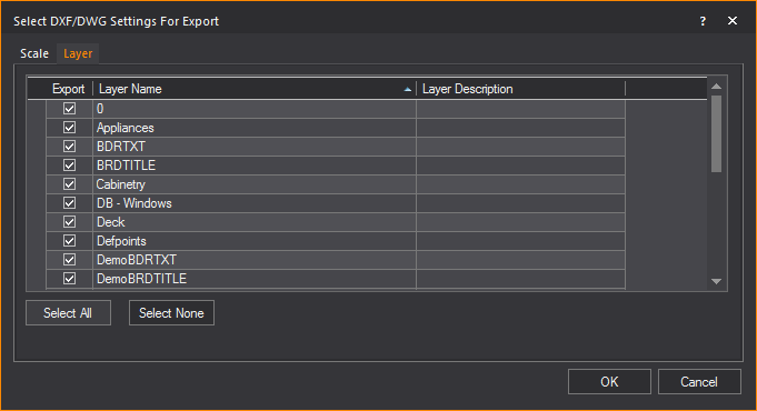
- Select the layers that you want to include in
the DWG/DXF drawing by highlighting them and ensuring that the Export checkbox is checked.
- Click Select All to
select all the layers that are listed.
- Click Select None to
deselect all layers.
- Click OK.